Cirkit Designer
Your all-in-one circuit design IDE
Home /
Component Documentation
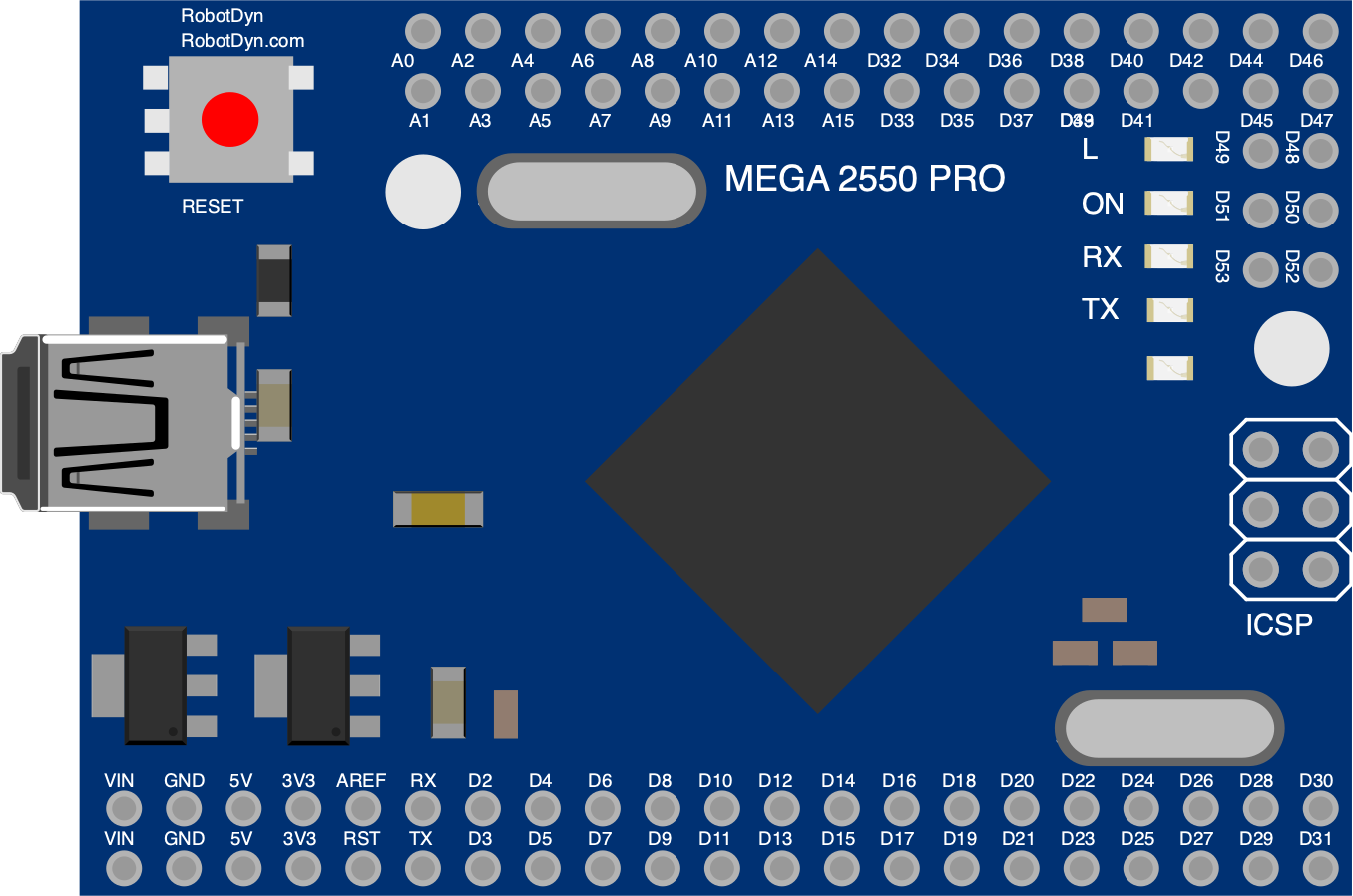
How to Use Mega2560 R3 Pro CH340G: Examples, Pinouts, and Specs
Introduction
The Mega2560 R3 Pro CH340G is a versatile microcontroller board based on the ATmega2560, which is well-suited for projects requiring a large number of I/O pins and more memory space. It is compatible with most shields designed for the Arduino Mega2560 R3. The inclusion of the CH340G USB-to-serial converter makes it an economical alternative to other boards for hobbyists and educators.
Explore Projects Built with Mega2560 R3 Pro CH340G
Arduino Mega 2560 Controlled RGB Panel Display with Bluetooth Connectivity and SD Card Logging
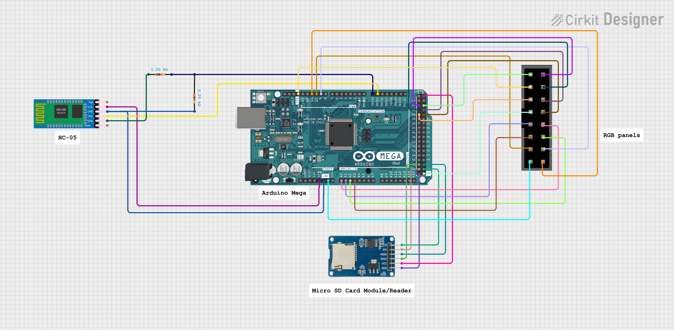
This circuit features an Arduino Mega 2560 microcontroller interfaced with an HC-05 Bluetooth module for wireless communication, and an RGB panel for display purposes. The Arduino also connects to a Micro SD Card Module for data storage. Voltage dividers using resistors are implemented for level shifting between the Arduino and the Bluetooth module, and the Arduino controls the RGB panel and communicates with the SD card using its digital and PWM pins.
Mega2560-Controlled Automation System with Non-Contact Liquid Level Sensing and Motor Control

This circuit appears to be a complex control system centered around an Arduino Mega2560 R3 Pro microcontroller, which interfaces with multiple sensors (XKC-Y26-V non-contact liquid level sensors and an LM35 temperature sensor), servo motors, a touch display, and an IBT-2 H-Bridge motor driver for controlling a planetary gearbox motor. The system also includes a UART TTL to RS485 converter for communication, likely with the touch display, and a power management subsystem with a switching power supply, fuses, and circuit breakers for safety and voltage regulation (XL4016). The absence of embedded code suggests that the functionality of the microcontroller is not defined within the provided data.
Multi-Functional Robotic Control System with Sensor Integration and Display Interface
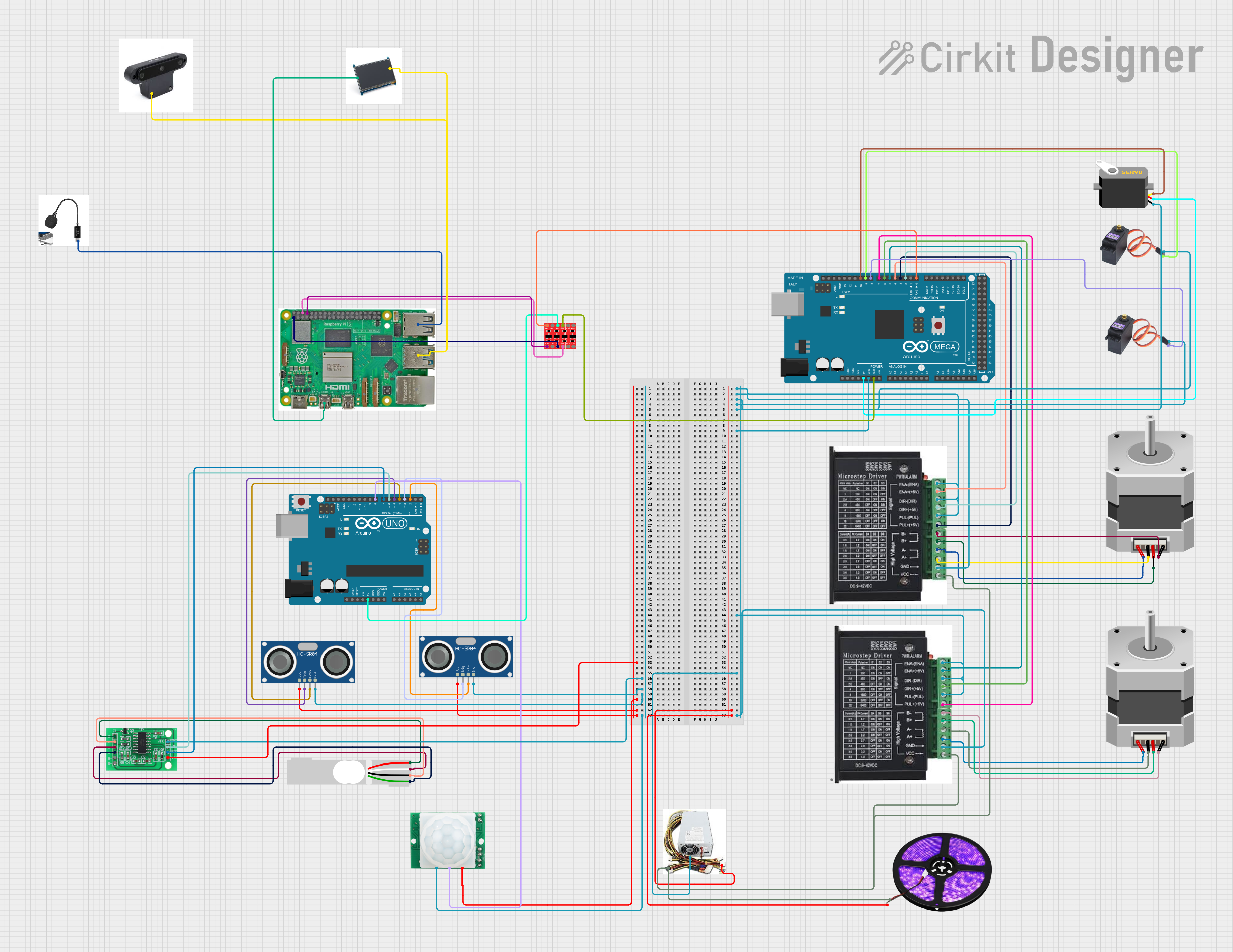
This circuit includes an Arduino Mega 2560 and an Arduino UNO microcontroller, both of which are connected to various sensors, actuators, and a power supply. The Mega 2560 controls stepper motors via drivers, servos, and an LED light strip, while the UNO interfaces with ultrasonic sensors, a motion sensor, and a load cell through an HX711 interface. Additionally, a Raspberry Pi 5 is connected to an LCD and peripherals, and a logic level converter is used for voltage level translation between devices.
Arduino Mega 2560 Controlled Multi-Temperature Monitoring and Motor Management System with Bluetooth Connectivity
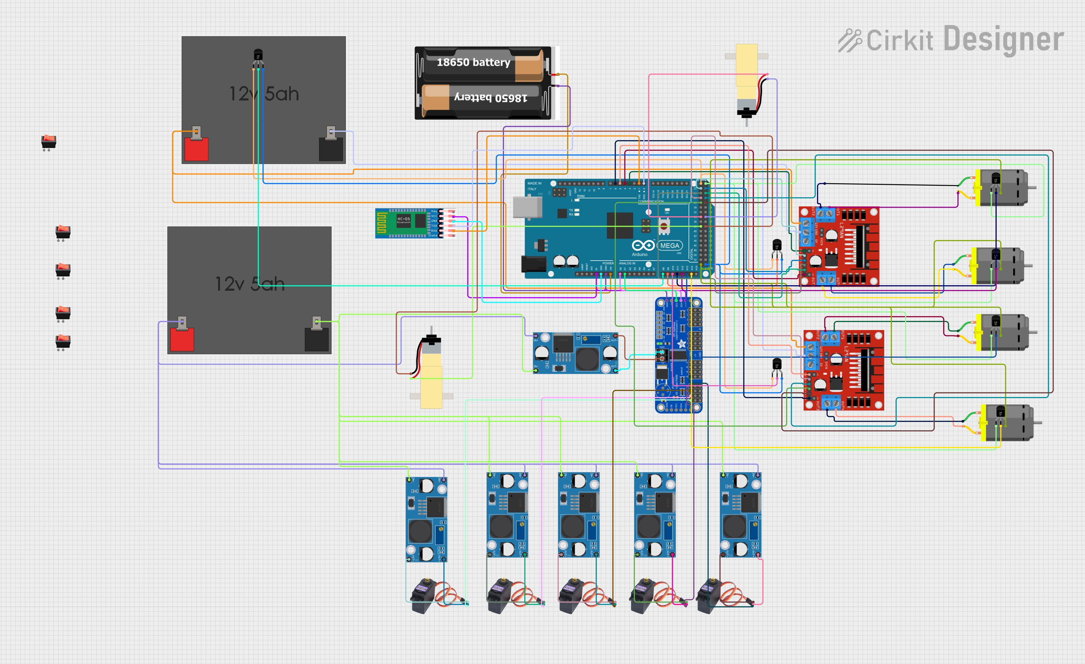
This is a multi-functional robotic control circuit that uses an Arduino Mega 2560 to manage servos and DC motors for movement, read temperatures from multiple sensors, and communicate wirelessly via Bluetooth. It is designed for applications requiring real-time monitoring and control, such as a robot or an automated system with environmental sensing capabilities.
Explore Projects Built with Mega2560 R3 Pro CH340G
Arduino Mega 2560 Controlled RGB Panel Display with Bluetooth Connectivity and SD Card Logging
This circuit features an Arduino Mega 2560 microcontroller interfaced with an HC-05 Bluetooth module for wireless communication, and an RGB panel for display purposes. The Arduino also connects to a Micro SD Card Module for data storage. Voltage dividers using resistors are implemented for level shifting between the Arduino and the Bluetooth module, and the Arduino controls the RGB panel and communicates with the SD card using its digital and PWM pins.
Mega2560-Controlled Automation System with Non-Contact Liquid Level Sensing and Motor Control
This circuit appears to be a complex control system centered around an Arduino Mega2560 R3 Pro microcontroller, which interfaces with multiple sensors (XKC-Y26-V non-contact liquid level sensors and an LM35 temperature sensor), servo motors, a touch display, and an IBT-2 H-Bridge motor driver for controlling a planetary gearbox motor. The system also includes a UART TTL to RS485 converter for communication, likely with the touch display, and a power management subsystem with a switching power supply, fuses, and circuit breakers for safety and voltage regulation (XL4016). The absence of embedded code suggests that the functionality of the microcontroller is not defined within the provided data.
Multi-Functional Robotic Control System with Sensor Integration and Display Interface
This circuit includes an Arduino Mega 2560 and an Arduino UNO microcontroller, both of which are connected to various sensors, actuators, and a power supply. The Mega 2560 controls stepper motors via drivers, servos, and an LED light strip, while the UNO interfaces with ultrasonic sensors, a motion sensor, and a load cell through an HX711 interface. Additionally, a Raspberry Pi 5 is connected to an LCD and peripherals, and a logic level converter is used for voltage level translation between devices.
Arduino Mega 2560 Controlled Multi-Temperature Monitoring and Motor Management System with Bluetooth Connectivity
This is a multi-functional robotic control circuit that uses an Arduino Mega 2560 to manage servos and DC motors for movement, read temperatures from multiple sensors, and communicate wirelessly via Bluetooth. It is designed for applications requiring real-time monitoring and control, such as a robot or an automated system with environmental sensing capabilities.
Common Applications and Use Cases
- Robotics
- 3D printers
- Home automation systems
- Complex control systems
- Educational projects and prototypes
Technical Specifications
Key Technical Details
- Microcontroller: ATmega2560
- Operating Voltage: 5V
- Input Voltage (recommended): 7-12V
- Input Voltage (limits): 6-20V
- Digital I/O Pins: 54 (of which 15 provide PWM output)
- Analog Input Pins: 16
- DC Current per I/O Pin: 20 mA
- DC Current for 3.3V Pin: 50 mA
- Flash Memory: 256 KB of which 8 KB used by bootloader
- SRAM: 8 KB
- EEPROM: 4 KB
- Clock Speed: 16 MHz
- LED_BUILTIN: Pin 13
Pin Configuration and Descriptions
| Pin Number | Function | Description |
|---|---|---|
| 1-54 | Digital I/O | Digital pins which can be used as input or output |
| A0-A15 | Analog Input | Analog pins which can be used to read analog voltages |
| 5V | Power Output | Provides 5V output (subject to current limitations) |
| 3.3V | Power Output | Provides 3.3V output (subject to current limitations) |
| GND | Ground | Ground pins |
| RST | Reset | Used to reset the microcontroller |
| TX0, RX0 | Serial 0 | Used for serial communication |
| SDA, SCL | I2C Data & Clock | Used for I2C communication |
| AREF | Analog Reference | Used to provide reference voltage for analog inputs |
| 3V3 | 3.3V Supply | 3.3V regulated output from the onboard regulator |
Usage Instructions
How to Use the Component in a Circuit
Powering the Board:
- Connect a 7-12V power supply to the VIN and GND pins, or plug a USB cable into the board's USB port.
Connecting I/O:
- Digital pins can be used as inputs or outputs. Set the mode in your code using
pinMode(pin, mode);. - Analog pins are primarily for input but can also serve as digital pins if needed.
- Digital pins can be used as inputs or outputs. Set the mode in your code using
Uploading Sketches:
- Connect the board to your computer using a USB cable.
- Select "Arduino Mega or Mega 2560" in the Arduino IDE.
- Choose the correct port for the CH340G under Tools > Port.
- Click "Upload" to send your sketch to the board.
Important Considerations and Best Practices
- Ensure that the power supply is within the recommended limits to avoid damaging the board.
- Do not draw more than 20 mA from any I/O pin.
- When using PWM, remember that not all digital pins support PWM output.
- Use external pull-up or pull-down resistors with inputs to ensure stable readings.
- Avoid connecting high-current devices directly; use external power sources and transistors or relays.
Troubleshooting and FAQs
Common Issues
- Driver Installation: The CH340G requires drivers to be installed on some computers. Ensure that the correct drivers are installed.
- Board Not Recognized: Check the USB cable and port. Try a different cable or port if necessary.
- Sketch Upload Failure: Ensure the correct board and port are selected in the Arduino IDE. Press the reset button on the board just before uploading if issues persist.
Solutions and Tips for Troubleshooting
- Driver Issues: Download and install the latest CH340 drivers from the manufacturer's website.
- Power Issues: If the board is unresponsive, check the power supply and connections.
- Connectivity Issues: Verify that the USB cable is fully inserted and functional.
Example Code for Arduino UNO
// Blink the onboard LED connected to pin 13
void setup() {
  pinMode(13, OUTPUT); // Set pin 13 as an output
}

void loop() {
  digitalWrite(13, HIGH);   // Turn the LED on
  delay(1000);              // Wait for a second
  digitalWrite(13, LOW);    // Turn the LED off
  delay(1000);              // Wait for a second
}
Note: The example code provided is for the Arduino UNO but is also compatible with the Mega2560 R3 Pro CH340G, as they share the same pin for the built-in LED.
For more advanced usage and additional examples, refer to the Arduino official documentation and community forums.