Cirkit Designer Logo
Cirkit Designer
Your all-in-one circuit design IDE
Home / 
Component Documentation

How to Use PCF8574: Examples, Pinouts, and Specs

Image of PCF8574
Cirkit Designer LogoDesign with PCF8574 in Cirkit Designer

Introduction

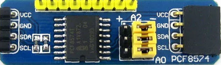
The PCF8574, manufactured by Texas Instruments, is an I2C I/O expander that provides 8 additional digital input/output pins to a microcontroller. This component is particularly useful in applications where the number of GPIO pins on a microcontroller is insufficient. By utilizing the I2C communication protocol, the PCF8574 allows for efficient control of multiple devices while minimizing the number of pins required on the microcontroller.

Explore Projects Built with PCF8574

Use Cirkit Designer to design, explore, and prototype these projects online. Some projects support real-time simulation. Click "Open Project" to start designing instantly!
Biometric and RFID Security System with Dual Adafruit Feather nRF52840 Controllers
Image of Rfid access control: A project utilizing PCF8574 in a practical application
This circuit features two Adafruit Feather nRF52840 microcontrollers, each interfaced with an RFID-RC522 module for RFID communication and an AT24C256 external EEPROM for additional memory storage. One of the microcontrollers is also connected to an R307 Fingerprint Sensor for biometric input, and both microcontrollers are powered by a shared power supply and a coin cell breakout for backup or RTC power. The circuit is likely designed for secure access control or identification purposes, utilizing both RFID and fingerprint authentication, with data storage capabilities.
Cirkit Designer LogoOpen Project in Cirkit Designer
Cellular-Enabled IoT Device with Real-Time Clock and Power Management
Image of LRCM PHASE 2 BASIC: A project utilizing PCF8574 in a practical application
This circuit features a LilyGo-SIM7000G module for cellular communication and GPS functionality, interfaced with an RTC DS3231 for real-time clock capabilities. It includes voltage sensing through two voltage sensor modules, and uses an 8-channel opto-coupler for isolating different parts of the circuit. Power management is handled by a buck converter connected to a DC power source and batteries, with a fuse for protection and a rocker switch for on/off control. Additionally, there's an LED for indication purposes.
Cirkit Designer LogoOpen Project in Cirkit Designer
Arduino UNO-Based Real-Time Clock with I2C LCD Display and IO Expansion
Image of teste: A project utilizing PCF8574 in a practical application
This circuit is an Arduino-based real-time clock and display system. It uses an Arduino UNO to interface with a DS1307 RTC module for timekeeping and a 20x4 I2C LCD to display the current time and date. Additionally, a PCF8574 IO Expansion Board is used to extend the I2C bus for additional I/O operations.
Cirkit Designer LogoOpen Project in Cirkit Designer
ESP32-Based Access Control System with Fingerprint and RFID Authentication
Image of SmartDoor: A project utilizing PCF8574 in a practical application
This circuit features an ESP32 microcontroller interfaced with a fingerprint scanner, RFID-RC522 module, a 12V solenoid lock, a buzzer, and an MKE-M07 LCD1602 I2C display. The ESP32 controls access through the solenoid lock based on authentication from the fingerprint scanner or RFID reader, provides feedback through the buzzer, and displays information on the LCD. A 5V relay is used to drive the solenoid lock, and the ESP32 manages the overall logic and communication between components.
Cirkit Designer LogoOpen Project in Cirkit Designer

Explore Projects Built with PCF8574

Use Cirkit Designer to design, explore, and prototype these projects online. Some projects support real-time simulation. Click "Open Project" to start designing instantly!
Image of Rfid access control: A project utilizing PCF8574 in a practical application
Biometric and RFID Security System with Dual Adafruit Feather nRF52840 Controllers
This circuit features two Adafruit Feather nRF52840 microcontrollers, each interfaced with an RFID-RC522 module for RFID communication and an AT24C256 external EEPROM for additional memory storage. One of the microcontrollers is also connected to an R307 Fingerprint Sensor for biometric input, and both microcontrollers are powered by a shared power supply and a coin cell breakout for backup or RTC power. The circuit is likely designed for secure access control or identification purposes, utilizing both RFID and fingerprint authentication, with data storage capabilities.
Cirkit Designer LogoOpen Project in Cirkit Designer
Image of LRCM PHASE 2 BASIC: A project utilizing PCF8574 in a practical application
Cellular-Enabled IoT Device with Real-Time Clock and Power Management
This circuit features a LilyGo-SIM7000G module for cellular communication and GPS functionality, interfaced with an RTC DS3231 for real-time clock capabilities. It includes voltage sensing through two voltage sensor modules, and uses an 8-channel opto-coupler for isolating different parts of the circuit. Power management is handled by a buck converter connected to a DC power source and batteries, with a fuse for protection and a rocker switch for on/off control. Additionally, there's an LED for indication purposes.
Cirkit Designer LogoOpen Project in Cirkit Designer
Image of teste: A project utilizing PCF8574 in a practical application
Arduino UNO-Based Real-Time Clock with I2C LCD Display and IO Expansion
This circuit is an Arduino-based real-time clock and display system. It uses an Arduino UNO to interface with a DS1307 RTC module for timekeeping and a 20x4 I2C LCD to display the current time and date. Additionally, a PCF8574 IO Expansion Board is used to extend the I2C bus for additional I/O operations.
Cirkit Designer LogoOpen Project in Cirkit Designer
Image of SmartDoor: A project utilizing PCF8574 in a practical application
ESP32-Based Access Control System with Fingerprint and RFID Authentication
This circuit features an ESP32 microcontroller interfaced with a fingerprint scanner, RFID-RC522 module, a 12V solenoid lock, a buzzer, and an MKE-M07 LCD1602 I2C display. The ESP32 controls access through the solenoid lock based on authentication from the fingerprint scanner or RFID reader, provides feedback through the buzzer, and displays information on the LCD. A 5V relay is used to drive the solenoid lock, and the ESP32 manages the overall logic and communication between components.
Cirkit Designer LogoOpen Project in Cirkit Designer

Common Applications and Use Cases

  • Expanding GPIO pins for microcontrollers in resource-constrained systems
  • Driving LEDs, relays, or other digital outputs
  • Reading digital inputs such as switches or sensors
  • Home automation systems
  • Industrial control systems
  • Keypad interfacing

Technical Specifications

The following table outlines the key technical details of the PCF8574:

Parameter Value
Operating Voltage Range 2.5V to 6V
Maximum Sink Current (per pin) 25 mA
Maximum Source Current (per pin) -300 µA
Communication Protocol I2C (2-wire)
I2C Address Range 0x20 to 0x27 (configurable via A0, A1, A2)
Number of I/O Pins 8
Operating Temperature Range -40°C to 85°C
Package Types SOIC, PDIP, TSSOP

Pin Configuration and Descriptions

The PCF8574 has 16 pins, with the following configuration:

Pin Number Pin Name Description
1 A0 I2C Address Selection Bit 0
2 A1 I2C Address Selection Bit 1
3 A2 I2C Address Selection Bit 2
4 P0 General Purpose I/O Pin 0
5 P1 General Purpose I/O Pin 1
6 P2 General Purpose I/O Pin 2
7 P3 General Purpose I/O Pin 3
8 VSS Ground (0V)
9 P4 General Purpose I/O Pin 4
10 P5 General Purpose I/O Pin 5
11 P6 General Purpose I/O Pin 6
12 P7 General Purpose I/O Pin 7
13 INT Interrupt Output (active low)
14 SCL I2C Clock Line
15 SDA I2C Data Line
16 VDD Power Supply (2.5V to 6V)

Usage Instructions

How to Use the PCF8574 in a Circuit

  1. Power Supply: Connect the VDD pin to a power source (2.5V to 6V) and the VSS pin to ground.
  2. I2C Address Configuration: Use the A0, A1, and A2 pins to set the I2C address. These pins can be connected to VDD (logic high) or VSS (logic low) to configure the address.
  3. I2C Communication: Connect the SCL and SDA pins to the corresponding I2C lines on the microcontroller. Pull-up resistors (typically 4.7kΩ) are required on these lines.
  4. GPIO Usage: Use the P0–P7 pins as digital inputs or outputs. When configured as outputs, these pins can drive LEDs, relays, or other devices. When configured as inputs, they can read the state of switches or sensors.
  5. Interrupt Pin: The INT pin can be used to signal the microcontroller when an input pin state changes. This is particularly useful for event-driven applications.

Important Considerations and Best Practices

  • Pull-Up Resistors: Ensure proper pull-up resistors are used on the I2C lines (SCL and SDA) to maintain signal integrity.
  • Current Limitations: Avoid exceeding the maximum sink current (25 mA per pin) to prevent damage to the device.
  • Address Conflicts: If multiple PCF8574 devices are used on the same I2C bus, ensure each device has a unique address by configuring the A0, A1, and A2 pins appropriately.
  • Interrupt Handling: If using the INT pin, ensure the microcontroller is configured to handle external interrupts.

Example Code for Arduino UNO

Below is an example of how to use the PCF8574 with an Arduino UNO to toggle an LED connected to pin P0:

#include <Wire.h> // Include the Wire library for I2C communication

#define PCF8574_ADDRESS 0x20 // Default I2C address of the PCF8574

void setup() {
  Wire.begin(); // Initialize I2C communication
  Serial.begin(9600); // Initialize serial communication for debugging

  // Set all pins of PCF8574 to HIGH (default state)
  Wire.beginTransmission(PCF8574_ADDRESS);
  Wire.write(0xFF); // All pins HIGH
  Wire.endTransmission();

  Serial.println("PCF8574 initialized.");
}

void loop() {
  // Toggle P0 (connected to an LED)
  Wire.beginTransmission(PCF8574_ADDRESS);
  Wire.write(0xFE); // Set P0 LOW, others HIGH
  Wire.endTransmission();
  delay(500); // Wait for 500ms

  Wire.beginTransmission(PCF8574_ADDRESS);
  Wire.write(0xFF); // Set all pins HIGH
  Wire.endTransmission();
  delay(500); // Wait for 500ms
}

Troubleshooting and FAQs

Common Issues and Solutions

  1. I2C Communication Failure:

    • Cause: Incorrect wiring or missing pull-up resistors on the SDA and SCL lines.
    • Solution: Verify the connections and ensure pull-up resistors (4.7kΩ) are present.
  2. Device Not Responding:

    • Cause: Incorrect I2C address configuration.
    • Solution: Check the A0, A1, and A2 pin connections and ensure the correct address is used in the code.
  3. GPIO Pins Not Functioning as Expected:

    • Cause: Exceeding the current limits or incorrect pin configuration.
    • Solution: Ensure the current drawn by connected devices does not exceed 25 mA per pin. Verify the pin states in the code.
  4. Interrupt Pin Not Triggering:

    • Cause: Interrupts not enabled or incorrect wiring.
    • Solution: Ensure the INT pin is connected to the appropriate interrupt-capable pin on the microcontroller and that interrupts are enabled in the code.

FAQs

  • Can the PCF8574 be used with 3.3V microcontrollers? Yes, the PCF8574 is compatible with 3.3V systems as long as the VDD voltage is within the operating range (2.5V to 6V).

  • How many PCF8574 devices can be connected to a single I2C bus? Up to 8 devices can be connected, as the I2C address range (0x20 to 0x27) allows for 8 unique addresses.

  • Can the PCF8574 handle analog signals? No, the PCF8574 is designed for digital input/output only.

  • What happens if the INT pin is not used? The INT pin can be left unconnected if interrupt functionality is not required.