Cirkit Designer Logo
Cirkit Designer
Your all-in-one circuit design IDE
Home / 
Component Documentation

How to Use Adafruit TXB0108 8-channel Bi-directional Logic Level Converter: Examples, Pinouts, and Specs

Image of Adafruit TXB0108 8-channel Bi-directional Logic Level Converter
Cirkit Designer LogoDesign with Adafruit TXB0108 8-channel Bi-directional Logic Level Converter in Cirkit Designer

Introduction

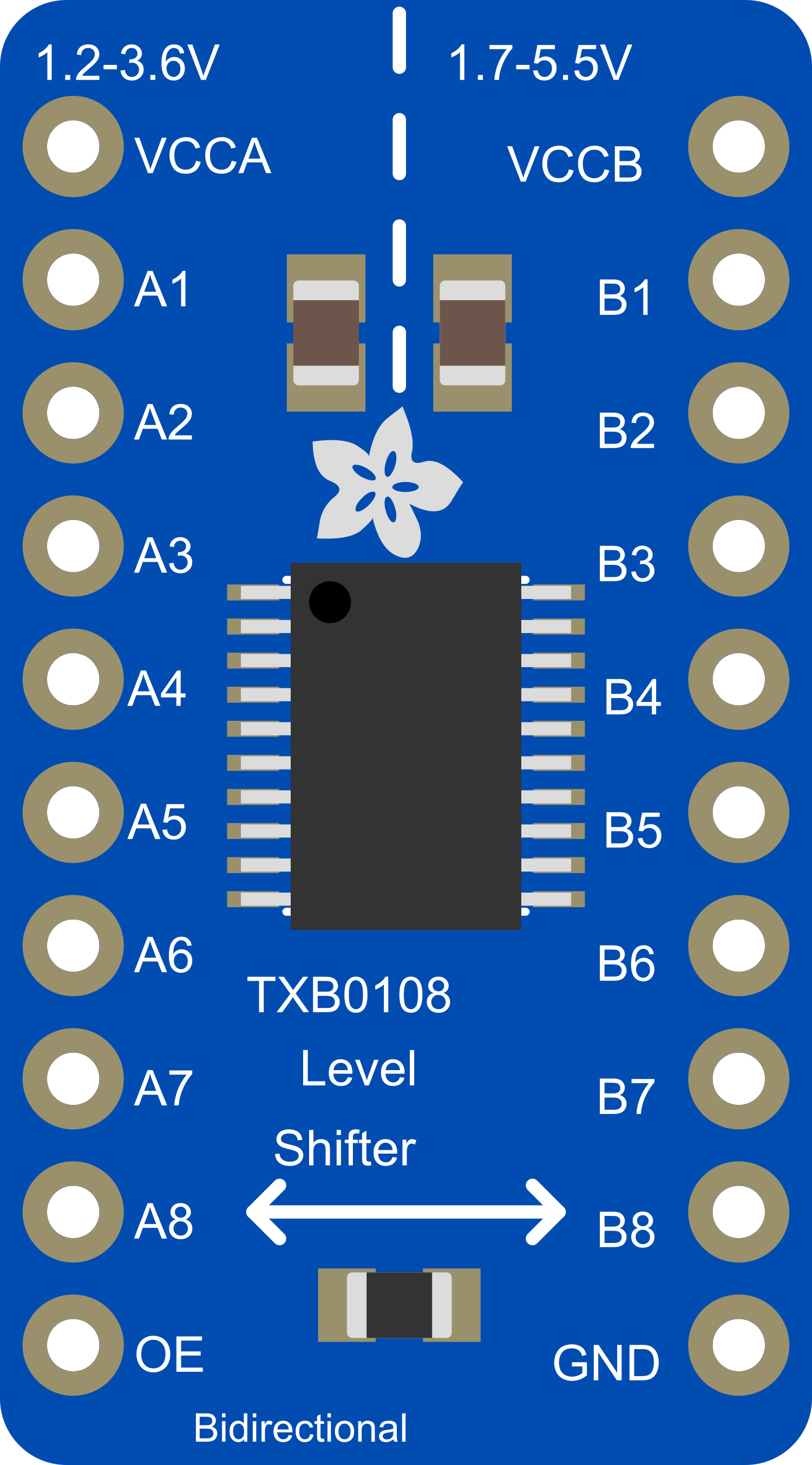
The Adafruit TXB0108 8-channel Bi-directional Logic Level Converter is a versatile breakout board designed for interfacing between circuits operating at different voltage levels. It is capable of bidirectional level shifting, making it suitable for use in applications where communication between low-voltage and high-voltage devices is necessary. This component is particularly useful in scenarios where microcontrollers like the Arduino UNO (operating at 5V) need to communicate with modern sensors or other ICs that operate at lower voltages (e.g., 3.3V).

Explore Projects Built with Adafruit TXB0108 8-channel Bi-directional Logic Level Converter

Use Cirkit Designer to design, explore, and prototype these projects online. Some projects support real-time simulation. Click "Open Project" to start designing instantly!
Wi-Fi Controlled Device Interface with Wemos D1 Mini and Logic Level Converter
Image of Toshiba AC D1 mini: A project utilizing Adafruit TXB0108 8-channel Bi-directional Logic Level Converter in a practical application
This circuit features a Wemos D1 Mini microcontroller interfaced with a Bi-Directional Logic Level Converter to facilitate communication with a 5V RX/TX module. The level converter ensures proper voltage translation between the 3.3V logic of the Wemos D1 Mini and the 5V logic of the RX/TX module.
Cirkit Designer LogoOpen Project in Cirkit Designer
Arduino Mega 2560 Controlled Motor System with I2C Communication and Hall Effect Sensing
Image of Uni1: A project utilizing Adafruit TXB0108 8-channel Bi-directional Logic Level Converter in a practical application
This is a motor control system with feedback and sensor integration. It uses an Arduino Mega 2560 to control MD03 motor drivers for DC motors, receives position and speed feedback from HEDS encoders and Hall sensors, and measures distance with SR02 ultrasonic sensors. Logic level converters ensure compatibility between different voltage levels of the components.
Cirkit Designer LogoOpen Project in Cirkit Designer
Wi-Fi Controlled LED Display with ESP32 and WS2812B
Image of Shop Uplights: A project utilizing Adafruit TXB0108 8-channel Bi-directional Logic Level Converter in a practical application
This circuit uses an ESP32 microcontroller to control an addressable LED pixel board (WS2812B) through a bi-directional logic level converter, ensuring proper voltage levels. The entire system is powered by a DC power source, with all components sharing a common ground.
Cirkit Designer LogoOpen Project in Cirkit Designer
ESP32 and Logic Level Converter-Based Wi-Fi Controlled Interface
Image of Toshiba AC ESP32 devkit v1: A project utilizing Adafruit TXB0108 8-channel Bi-directional Logic Level Converter in a practical application
This circuit features an ESP32 Devkit V1 microcontroller connected to a Bi-Directional Logic Level Converter, which facilitates voltage level shifting between the ESP32 and external components. The ESP32 is powered through its VIN pin via an alligator clip cable, and the logic level converter is connected to various pins on the ESP32 to manage different voltage levels for communication.
Cirkit Designer LogoOpen Project in Cirkit Designer

Explore Projects Built with Adafruit TXB0108 8-channel Bi-directional Logic Level Converter

Use Cirkit Designer to design, explore, and prototype these projects online. Some projects support real-time simulation. Click "Open Project" to start designing instantly!
Image of Toshiba AC D1 mini: A project utilizing Adafruit TXB0108 8-channel Bi-directional Logic Level Converter in a practical application
Wi-Fi Controlled Device Interface with Wemos D1 Mini and Logic Level Converter
This circuit features a Wemos D1 Mini microcontroller interfaced with a Bi-Directional Logic Level Converter to facilitate communication with a 5V RX/TX module. The level converter ensures proper voltage translation between the 3.3V logic of the Wemos D1 Mini and the 5V logic of the RX/TX module.
Cirkit Designer LogoOpen Project in Cirkit Designer
Image of Uni1: A project utilizing Adafruit TXB0108 8-channel Bi-directional Logic Level Converter in a practical application
Arduino Mega 2560 Controlled Motor System with I2C Communication and Hall Effect Sensing
This is a motor control system with feedback and sensor integration. It uses an Arduino Mega 2560 to control MD03 motor drivers for DC motors, receives position and speed feedback from HEDS encoders and Hall sensors, and measures distance with SR02 ultrasonic sensors. Logic level converters ensure compatibility between different voltage levels of the components.
Cirkit Designer LogoOpen Project in Cirkit Designer
Image of Shop Uplights: A project utilizing Adafruit TXB0108 8-channel Bi-directional Logic Level Converter in a practical application
Wi-Fi Controlled LED Display with ESP32 and WS2812B
This circuit uses an ESP32 microcontroller to control an addressable LED pixel board (WS2812B) through a bi-directional logic level converter, ensuring proper voltage levels. The entire system is powered by a DC power source, with all components sharing a common ground.
Cirkit Designer LogoOpen Project in Cirkit Designer
Image of Toshiba AC ESP32 devkit v1: A project utilizing Adafruit TXB0108 8-channel Bi-directional Logic Level Converter in a practical application
ESP32 and Logic Level Converter-Based Wi-Fi Controlled Interface
This circuit features an ESP32 Devkit V1 microcontroller connected to a Bi-Directional Logic Level Converter, which facilitates voltage level shifting between the ESP32 and external components. The ESP32 is powered through its VIN pin via an alligator clip cable, and the logic level converter is connected to various pins on the ESP32 to manage different voltage levels for communication.
Cirkit Designer LogoOpen Project in Cirkit Designer

Common Applications and Use Cases

  • Interfacing 5V microcontrollers with 3.3V sensors
  • Connecting 3.3V peripherals to a 5V system
  • Data transfer between devices with different voltage domains
  • Prototyping with mixed-voltage systems

Technical Specifications

Key Technical Details

  • Voltage Levels: Bidirectional shifting between 1.2V to 3.6V on the low side and 1.65V to 5.5V on the high side
  • Channels: 8 bidirectional data paths
  • Current Transfer Rate: Up to 60 mA per channel
  • Dimensions: 0.5" x 0.75" x 0.1" inches (LxWxH)

Pin Configuration and Descriptions

Pin Name Description
OE Output Enable - Active High
GND Ground
A1-A8 Channels 1-8 for the low-voltage side
B1-B8 Channels 1-8 for the high-voltage side
LV Low-voltage reference (1.2V to 3.6V)
HV High-voltage reference (1.65V to 5.5V)

Usage Instructions

How to Use the Component in a Circuit

  1. Power Connections:

    • Connect the LV pin to the lower voltage power supply (e.g., 3.3V).
    • Connect the HV pin to the higher voltage power supply (e.g., 5V).
    • Connect the GND pin to the common ground of both power supplies.
  2. Signal Connections:

    • Connect the low-voltage device signals to A1-A8.
    • Connect the high-voltage device signals to B1-B8.
  3. Enable the Converter:

    • Set the OE pin high to enable the level shifter.

Important Considerations and Best Practices

  • Ensure that the power supplies are stable and within the specified voltage ranges before connecting them to the LV and HV pins.
  • Do not exceed the current transfer rate of 60 mA per channel to prevent damage to the device.
  • Avoid applying signals to the I/O pins before the power supplies are stable and the OE pin is set high.
  • Use bypass capacitors close to the LV and HV pins to filter out noise and provide a stable power supply.

Troubleshooting and FAQs

Common Issues Users Might Face

  • Signal Integrity Problems: Ensure that the connections are secure and that there is no excessive noise in the power supply lines.
  • Device Not Working: Check that the OE pin is set high to enable the level shifter. Also, verify that the power supplies are within the specified voltage ranges.

Solutions and Tips for Troubleshooting

  • If the level shifter is not functioning, double-check the power supply voltages and connections.
  • For signal integrity issues, consider using shorter connections and shielding to reduce noise.
  • Ensure that the OE pin is connected and set to a high logic level to enable the level shifter.

FAQs

Q: Can the TXB0108 be used with I2C or SPI communication? A: The TXB0108 is not recommended for use with I2C or SPI as it does not have the necessary pull-up resistors for these protocols.

Q: What happens if the OE pin is left floating? A: If the OE pin is left floating, the level shifter may not operate correctly. It should be tied to a high logic level to enable the device.

Q: Is it possible to use fewer than 8 channels? A: Yes, you can use as many channels as needed. Unused channels can be left unconnected.

Example Code for Arduino UNO

// Example code to demonstrate the use of the Adafruit TXB0108 with an Arduino UNO
// This example assumes a 3.3V sensor is connected to channel A1 and the Arduino is on channel B1

void setup() {
  pinMode(2, OUTPUT); // Arduino pin connected to B1 on the TXB0108
  digitalWrite(2, LOW); // Initialize the pin to LOW
}

void loop() {
  // Send a HIGH signal to the 3.3V sensor through the level shifter
  digitalWrite(2, HIGH);
  delay(1000); // Wait for 1 second
  // Send a LOW signal to the 3.3V sensor through the level shifter
  digitalWrite(2, LOW);
  delay(1000); // Wait for 1 second
}

Remember to adjust the pin numbers and logic levels according to your specific application and circuit design.