How to Use Pressure Sensor: Examples, Pinouts, and Specs
Introduction
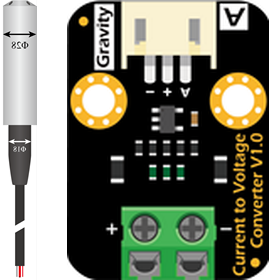
The DFRobot Pressure Sensor (Part ID: KIT0139) is a versatile device designed to measure the pressure of gases or liquids and convert it into an electrical signal. This sensor is ideal for applications requiring precise pressure monitoring or control, such as industrial automation, environmental monitoring, and fluid dynamics systems. Its compact design and reliable performance make it suitable for both hobbyist and professional projects.
Explore Projects Built with Pressure Sensor

Explore Projects Built with Pressure Sensor
Common Applications
- Industrial process control and automation
- Weather stations and environmental monitoring
- Hydraulic and pneumatic systems
- Liquid level measurement
- Robotics and IoT projects
Technical Specifications
The following table outlines the key technical details of the DFRobot Pressure Sensor (KIT0139):
| Parameter | Specification |
|---|---|
| Operating Voltage | 5V DC |
| Output Signal | Analog voltage (0.5V to 4.5V) |
| Pressure Range | 0 to 1.2 MPa (MegaPascal) |
| Accuracy | ±1.5% Full Scale |
| Operating Temperature | -20°C to 85°C |
| Response Time | ≤2 ms |
| Connector Type | 3-pin JST |
| Dimensions | 38mm x 20mm x 15mm |
Pin Configuration
The DFRobot Pressure Sensor has a 3-pin JST connector. The pinout is as follows:
| Pin | Name | Description |
|---|---|---|
| 1 | VCC | Power supply (5V DC) |
| 2 | GND | Ground |
| 3 | OUT | Analog output signal (pressure reading) |
Usage Instructions
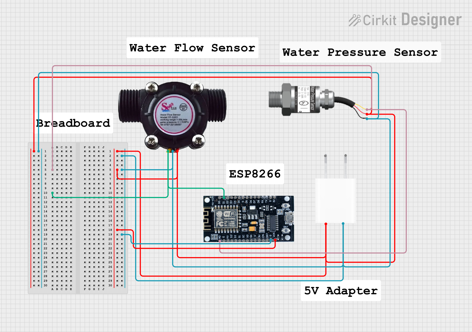
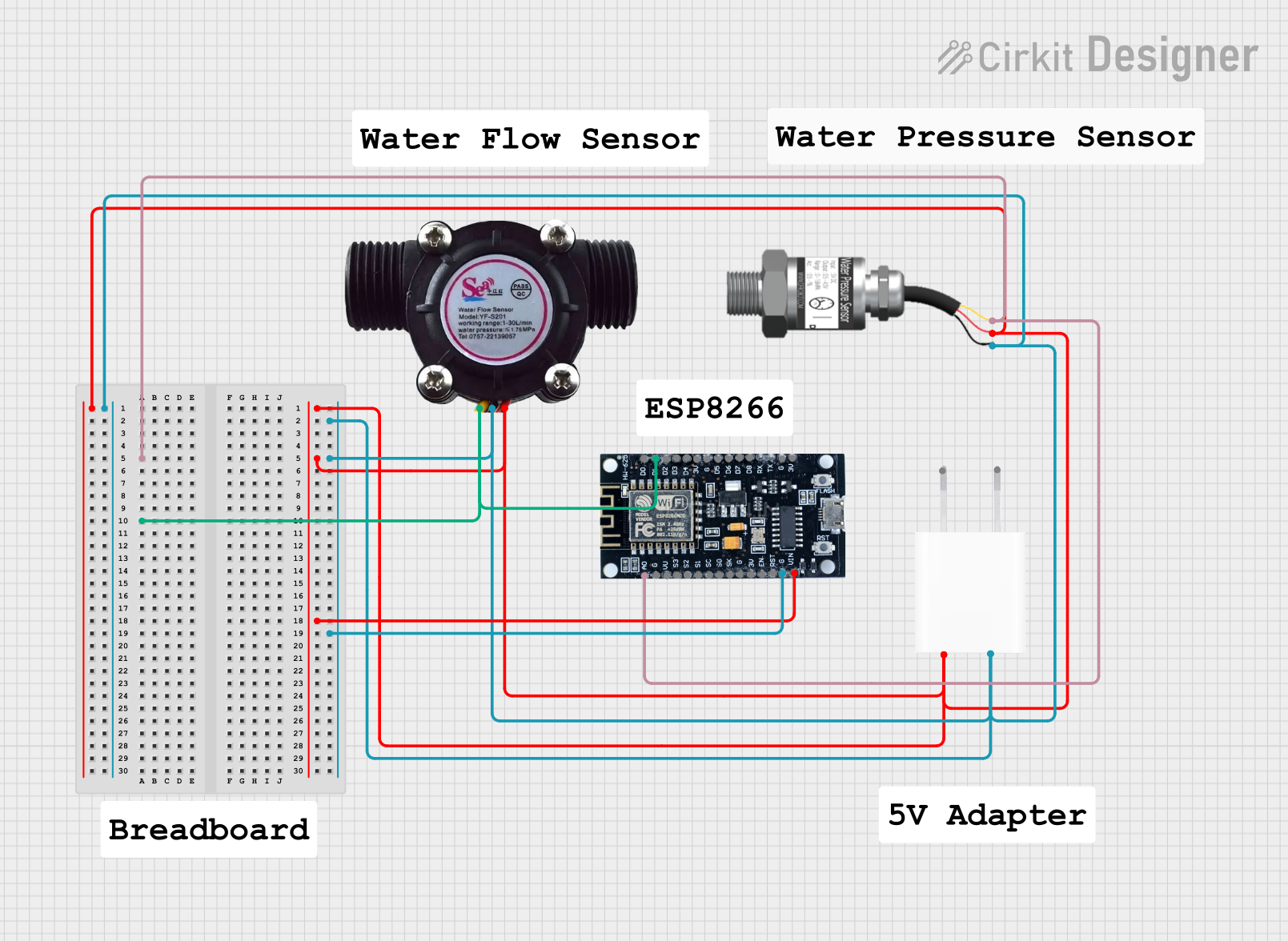
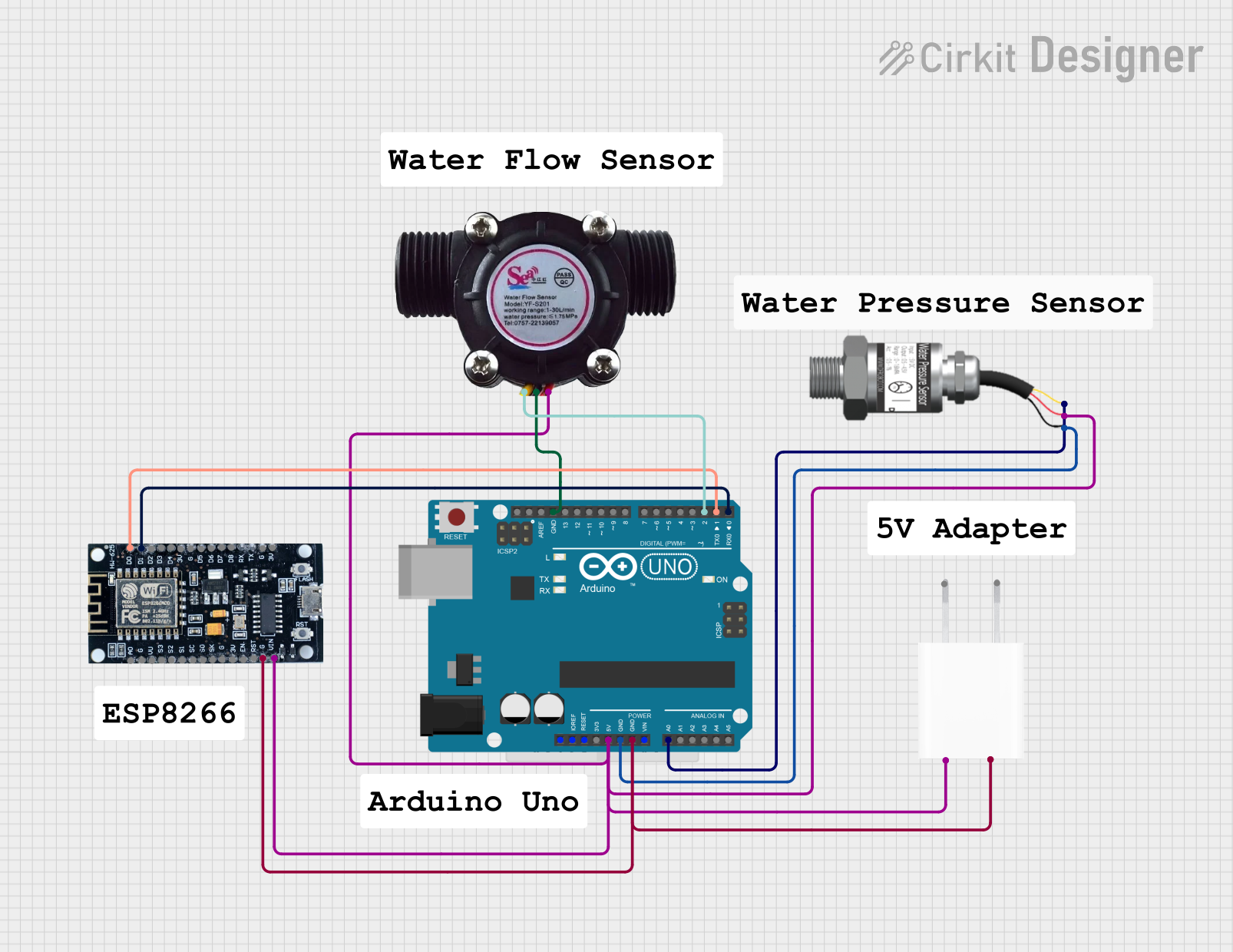
How to Use the Pressure Sensor in a Circuit
- Power the Sensor: Connect the
VCCpin to a 5V DC power source and theGNDpin to the ground of your circuit. - Read the Output: Connect the
OUTpin to an analog input pin of a microcontroller (e.g., Arduino UNO) to read the pressure data. - Calibrate the Sensor: The sensor outputs a voltage proportional to the pressure. At 0 MPa, the output is approximately 0.5V, and at 1.2 MPa, the output is approximately 4.5V. Use this range to map the voltage to pressure values in your code.
Important Considerations
- Ensure the sensor is not exposed to pressures beyond its maximum range (1.2 MPa) to avoid damage.
- Avoid exposing the sensor to corrosive or highly viscous fluids unless it is specifically rated for such use.
- Use proper decoupling capacitors near the sensor to reduce noise in the output signal.
Example Code for Arduino UNO
The following code demonstrates how to interface the DFRobot Pressure Sensor with an Arduino UNO to read and display pressure values:
// Define the analog pin connected to the sensor's OUT pin
const int pressurePin = A0;

// Define the pressure range in MPa
const float minPressure = 0.0;  // Minimum pressure (MPa)
const float maxPressure = 1.2; // Maximum pressure (MPa)

// Define the sensor's output voltage range
const float minVoltage = 0.5;  // Voltage at 0 MPa
const float maxVoltage = 4.5;  // Voltage at 1.2 MPa

void setup() {
  Serial.begin(9600); // Initialize serial communication
}

void loop() {
  // Read the analog value from the sensor
  int sensorValue = analogRead(pressurePin);

  // Convert the analog value to voltage (assuming 5V reference)
  float voltage = sensorValue * (5.0 / 1023.0);

  // Map the voltage to pressure in MPa
  float pressure = (voltage - minVoltage) * (maxPressure - minPressure) /
                   (maxVoltage - minVoltage) + minPressure;

  // Print the pressure value to the Serial Monitor
  Serial.print("Pressure: ");
  Serial.print(pressure);
  Serial.println(" MPa");

  delay(500); // Wait for 500ms before the next reading
}
Notes:
- Ensure the Arduino UNO is powered via USB or an external power source.
- Use a stable 5V power supply for the sensor to ensure accurate readings.
Troubleshooting and FAQs
Common Issues and Solutions
No Output Signal:
- Verify that the sensor is properly powered (check the
VCCandGNDconnections). - Ensure the
OUTpin is correctly connected to the microcontroller's analog input.
- Verify that the sensor is properly powered (check the
Inaccurate Readings:
- Check for noise in the power supply and add decoupling capacitors if necessary.
- Ensure the sensor is not exposed to temperatures or pressures outside its operating range.
Fluctuating Output:
- Verify that the sensor is securely mounted and not subject to vibrations.
- Use software filtering (e.g., averaging multiple readings) to smooth out the data.
FAQs
Q: Can this sensor measure negative pressure (vacuum)?
A: No, the DFRobot Pressure Sensor (KIT0139) is designed to measure positive pressure only, within the range of 0 to 1.2 MPa.
Q: Is the sensor waterproof?
A: The sensor is designed to measure the pressure of liquids and gases, but it should not be submerged unless specified by the manufacturer.
Q: Can I use this sensor with a 3.3V microcontroller?
A: The sensor requires a 5V power supply. If your microcontroller operates at 3.3V, you may need a level shifter for the output signal.
Q: How do I calibrate the sensor?
A: Use the sensor's output voltage range (0.5V to 4.5V) and map it to the pressure range (0 to 1.2 MPa) in your code, as shown in the example.
By following this documentation, you can effectively integrate the DFRobot Pressure Sensor (KIT0139) into your projects for accurate and reliable pressure measurements.