How to Use PIC32cmls000: Examples, Pinouts, and Specs
Introduction
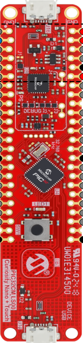
The PIC32cmls000 is a 32-bit microcontroller developed by Microchip Technology. It is based on the MIPS architecture and is designed to deliver high performance while maintaining low power consumption. This microcontroller integrates a variety of peripherals and connectivity options, making it ideal for a wide range of embedded applications.
Explore Projects Built with PIC32cmls000

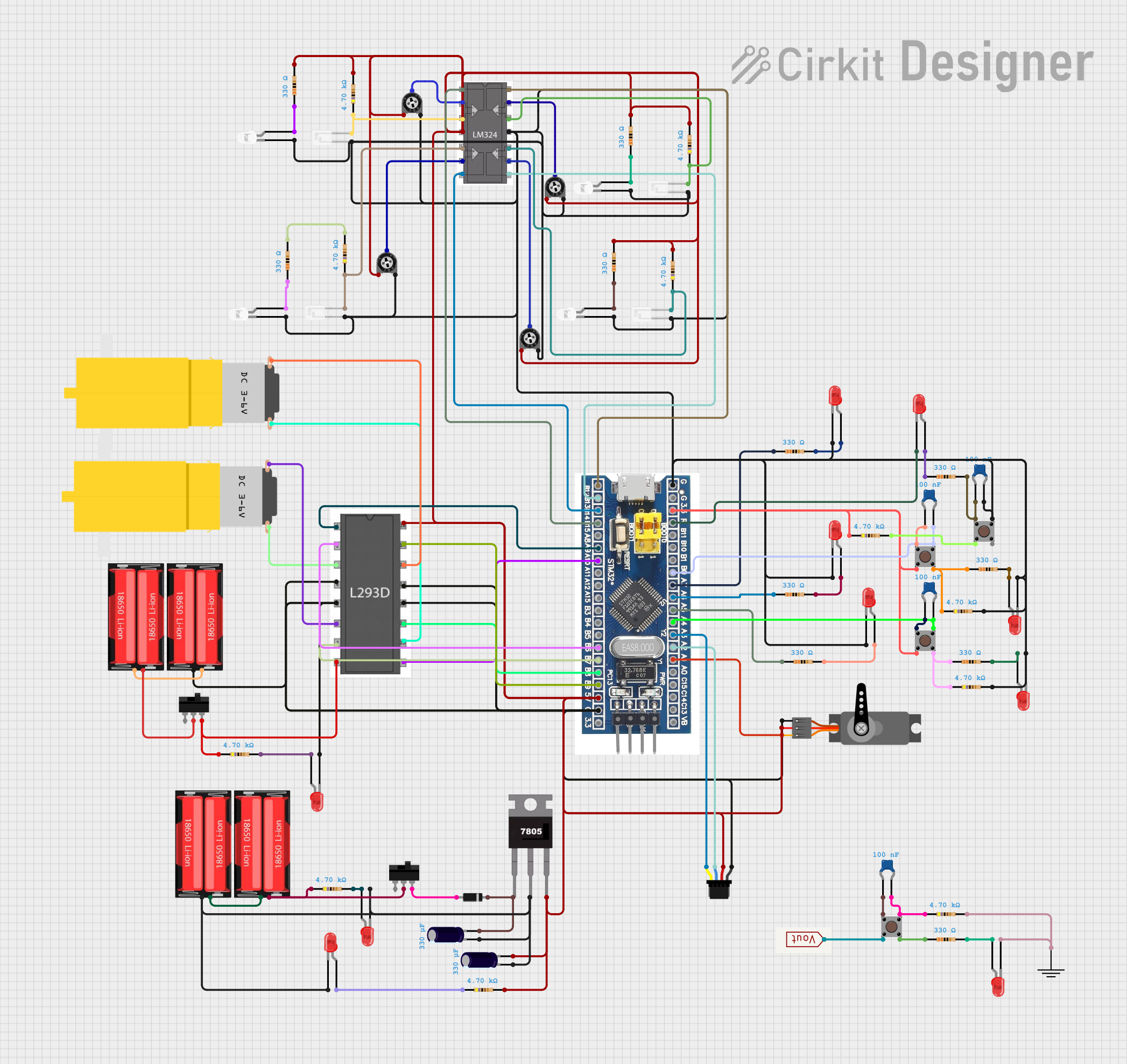
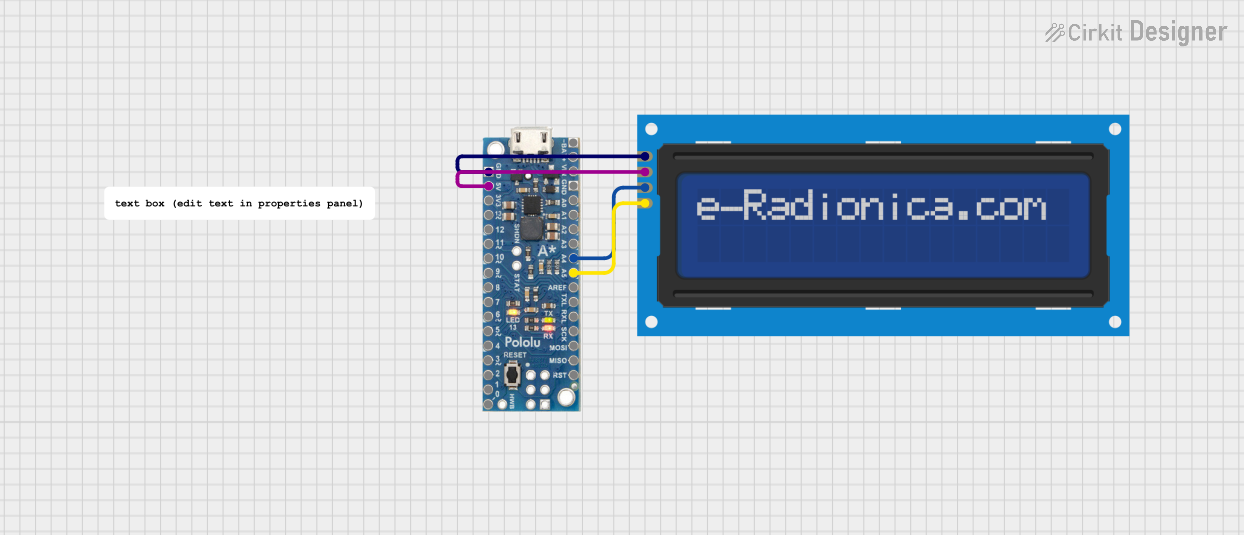
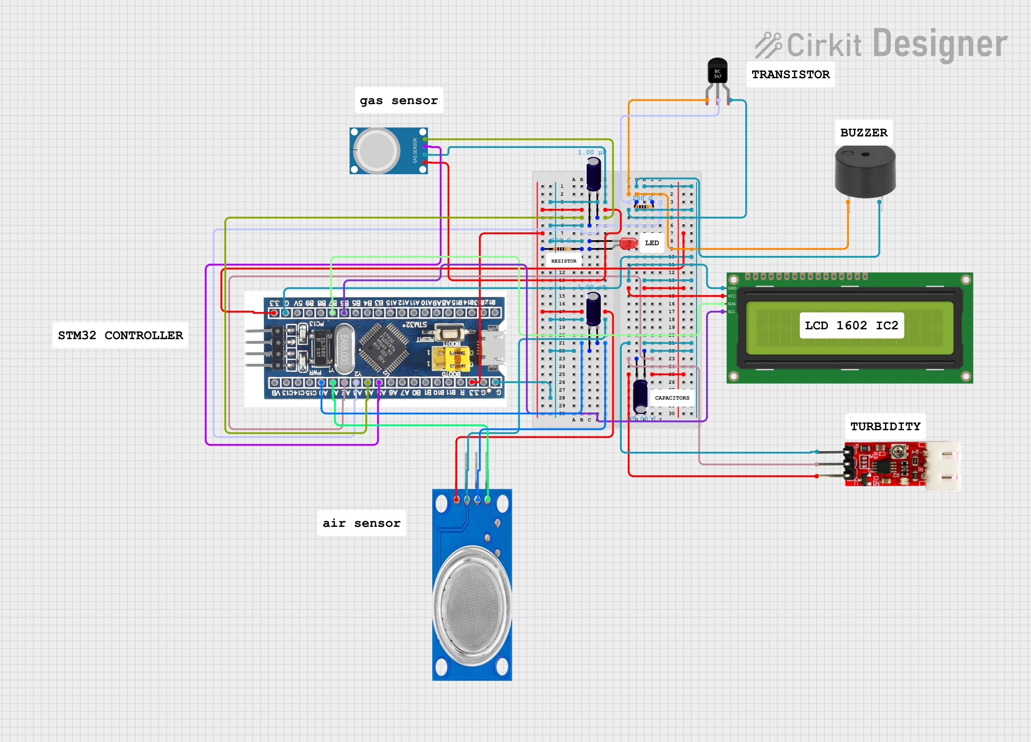
Explore Projects Built with PIC32cmls000
Common Applications and Use Cases
- Industrial automation and control systems
- IoT (Internet of Things) devices
- Consumer electronics
- Medical devices
- Automotive systems
- Data acquisition and processing
Technical Specifications
Key Technical Details
| Parameter | Value |
|---|---|
| Architecture | 32-bit MIPS |
| Operating Voltage | 2.3V to 3.6V |
| Maximum Clock Speed | 48 MHz |
| Flash Memory | Up to 128 KB |
| SRAM | Up to 32 KB |
| GPIO Pins | Up to 25 |
| Communication Interfaces | UART, SPI, I²C |
| Timers | 16-bit and 32-bit timers |
| ADC Resolution | 12-bit, up to 16 channels |
| Power Consumption | Low-power modes available (down to µA) |
| Package Options | QFN, TQFP |
Pin Configuration and Descriptions
Below is a general pinout description for the PIC32cmls000. Refer to the datasheet for the exact pin configuration based on the package type.
| Pin Number | Pin Name | Description |
|---|---|---|
| 1 | VDD | Power supply (2.3V to 3.6V) |
| 2 | VSS | Ground |
| 3 | GPIO1/AN0 | General-purpose I/O / Analog input 0 |
| 4 | GPIO2/AN1 | General-purpose I/O / Analog input 1 |
| 5 | UART_TX | UART Transmit |
| 6 | UART_RX | UART Receive |
| 7 | SPI_MOSI | SPI Master Out Slave In |
| 8 | SPI_MISO | SPI Master In Slave Out |
| 9 | SPI_SCK | SPI Clock |
| 10 | I²C_SDA | I²C Data Line |
| 11 | I²C_SCL | I²C Clock Line |
| 12 | ADC_IN0 | Analog-to-Digital Converter Input 0 |
| 13 | ADC_IN1 | Analog-to-Digital Converter Input 1 |
| 14 | RESET | Reset Pin |
| 15 | OSC1 | External Oscillator Input |
| 16 | OSC2 | External Oscillator Output |
Note: The exact pinout may vary depending on the package type (e.g., QFN, TQFP). Always consult the official datasheet for precise details.
Usage Instructions
How to Use the PIC32cmls000 in a Circuit
- Power Supply: Connect the VDD pin to a regulated power supply (2.3V to 3.6V) and the VSS pin to ground.
- Clock Configuration: Use an external crystal oscillator connected to the OSC1 and OSC2 pins, or configure the internal oscillator if available.
- Programming: Use a compatible programmer/debugger (e.g., Microchip's MPLAB ICD 4) to upload firmware via the ICSP (In-Circuit Serial Programming) interface.
- Peripheral Connections:
- For UART communication, connect the UART_TX and UART_RX pins to the corresponding pins of the external device.
- For SPI, connect SPI_MOSI, SPI_MISO, and SPI_SCK to the SPI bus.
- For I²C, connect I²C_SDA and I²C_SCL to the I²C bus with appropriate pull-up resistors.
- GPIO Usage: Configure GPIO pins as input or output in the firmware, depending on the application.
Important Considerations and Best Practices
- Decoupling Capacitors: Place decoupling capacitors (e.g., 0.1 µF) close to the VDD pin to reduce noise and ensure stable operation.
- Unused Pins: Configure unused pins as inputs with internal pull-ups enabled or tie them to ground to avoid floating states.
- Low-Power Modes: Utilize the microcontroller's low-power modes to reduce power consumption in battery-operated applications.
- Programming Voltage: Ensure the programming voltage is within the specified range to avoid damaging the microcontroller.
Example Code for Arduino UNO Integration
Although the PIC32cmls000 is not directly compatible with Arduino IDE, it can communicate with an Arduino UNO via UART. Below is an example of how to send data from the Arduino to the PIC32cmls000.
Arduino Code
void setup() {
  Serial.begin(9600); // Initialize UART communication at 9600 baud
}

void loop() {
  Serial.println("Hello, PIC32cmls000!"); // Send data to the PIC32
  delay(1000); // Wait for 1 second
}
PIC32cmls000 Code (Pseudocode)
#include <xc.h> // Include the PIC32 library

void UART_Init() {
    U1MODE = 0x8000; // Enable UART module
    U1BRG = 25;      // Set baud rate to 9600 (assuming 8 MHz clock)
    U1STA = 0x0400;  // Enable UART transmit
}

void UART_Read() {
    while (!U1STAbits.URXDA); // Wait for data to be received
    char receivedData = U1RXREG; // Read received data
    // Process the received data as needed
}

int main() {
    UART_Init(); // Initialize UART
    while (1) {
        UART_Read(); // Continuously read data from UART
    }
    return 0;
}
Note: The above PIC32 code is a simplified example. Refer to the PIC32cmls000 datasheet and Microchip's MPLAB X IDE for detailed implementation.
Troubleshooting and FAQs
Common Issues and Solutions
Microcontroller Not Powering On
- Cause: Incorrect power supply voltage or missing decoupling capacitors.
- Solution: Verify the power supply voltage is within the 2.3V to 3.6V range and add decoupling capacitors near the VDD pin.
Programming Failure
- Cause: Incorrect ICSP connections or incompatible programmer.
- Solution: Double-check the ICSP connections and ensure the programmer supports the PIC32cmls000.
UART Communication Not Working
- Cause: Mismatched baud rates or incorrect pin connections.
- Solution: Ensure both devices use the same baud rate and verify the UART_TX and UART_RX connections.
High Power Consumption
- Cause: Unused peripherals or pins left floating.
- Solution: Disable unused peripherals in the firmware and configure unused pins as inputs with pull-ups.
FAQs
Q: Can the PIC32cmls000 operate without an external oscillator?
A: Yes, the PIC32cmls000 can use its internal oscillator, but an external oscillator may be required for higher precision.
Q: What is the maximum GPIO current?
A: Each GPIO pin can source or sink up to 25 mA, but the total current should not exceed the microcontroller's maximum rating.
Q: Is the PIC32cmls000 suitable for battery-powered applications?
A: Yes, its low-power modes make it ideal for battery-operated devices.
Q: How do I debug my code on the PIC32cmls000?
A: Use Microchip's MPLAB X IDE and a compatible debugger (e.g., MPLAB ICD 4) for debugging.