How to Use GPS Neo 6m: Examples, Pinouts, and Specs
Introduction
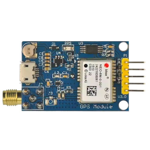
The GPS Neo 6M is a high-performance GPS module designed to provide accurate positioning data for a wide range of applications. Its compact design, low power consumption, and support for multiple communication protocols make it a popular choice for navigation, tracking, and location-based systems. The module is equipped with an onboard antenna and supports UART communication, making it easy to integrate into microcontroller-based projects.
Explore Projects Built with GPS Neo 6m

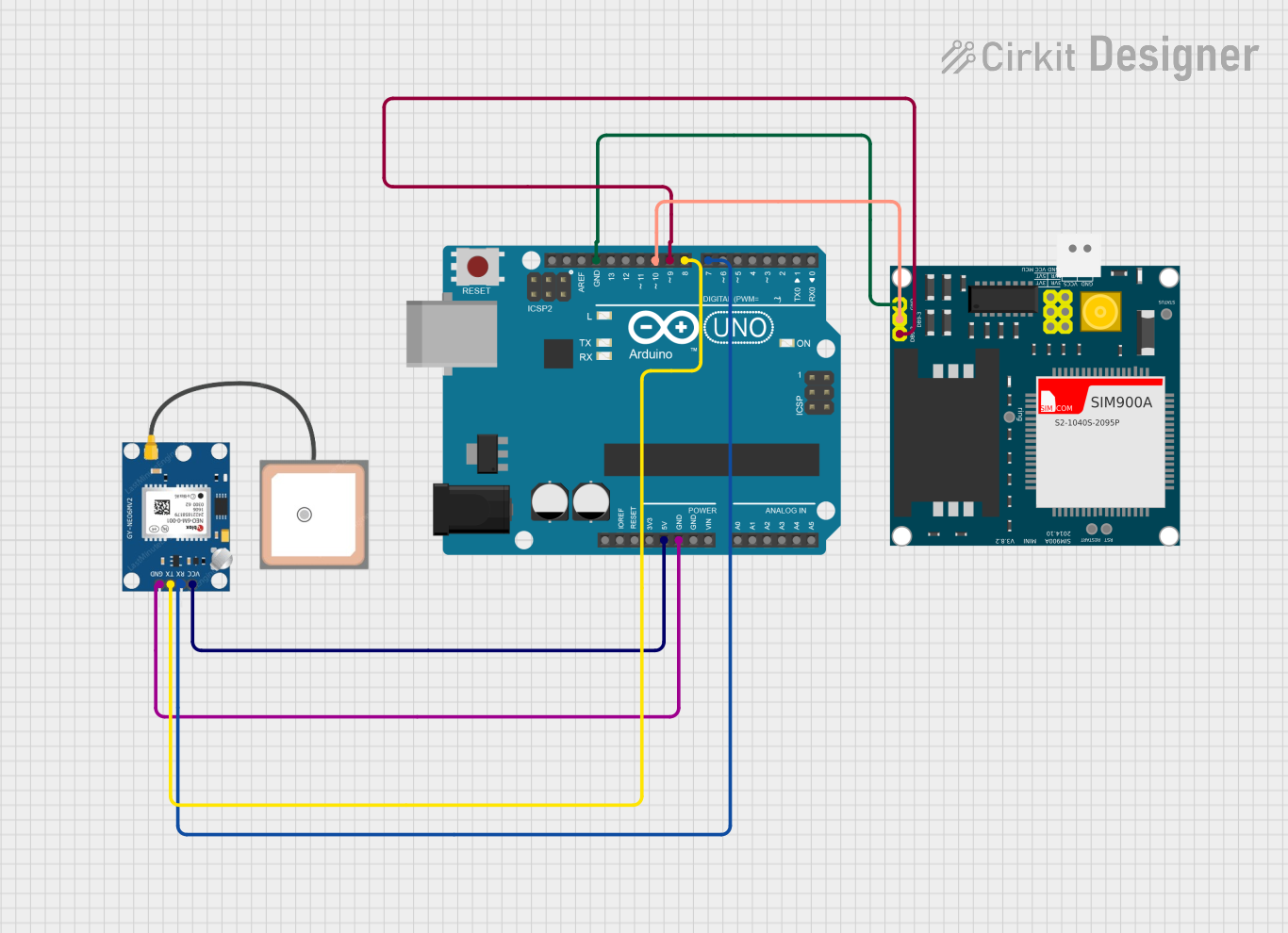
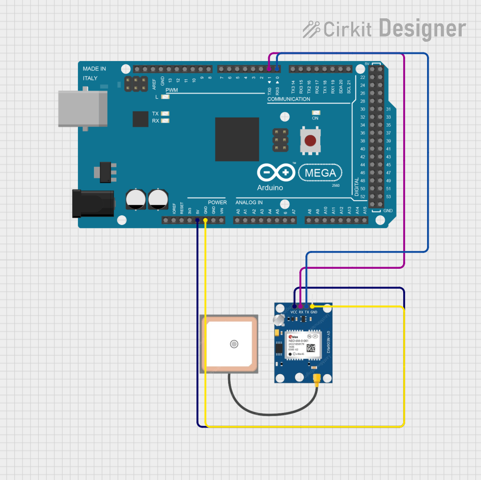
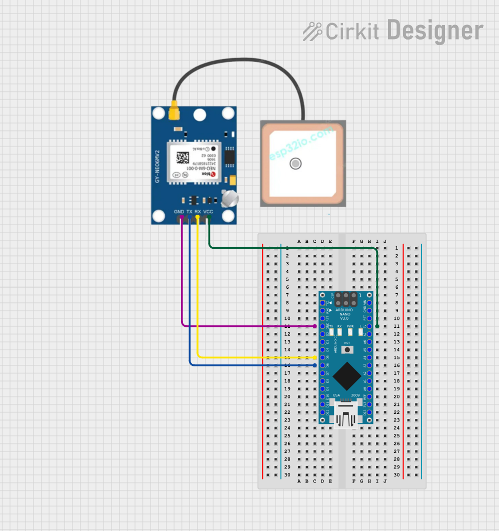
Explore Projects Built with GPS Neo 6m
Common Applications
- Vehicle tracking and navigation systems
- Drones and UAVs for location tracking
- Geocaching and outdoor navigation
- IoT devices requiring location data
- Robotics and autonomous systems
Technical Specifications
Below are the key technical details of the GPS Neo 6M module:
| Parameter | Specification |
|---|---|
| Operating Voltage | 2.7V to 3.6V (typically 3.3V) |
| Power Consumption | 45mA (typical) |
| Communication Interface | UART (default baud rate: 9600 bps) |
| Position Accuracy | 2.5 meters CEP (Circular Error Probable) |
| Update Rate | 1 Hz (configurable up to 5 Hz) |
| Operating Temperature | -40°C to +85°C |
| Dimensions | 16 x 12.2 x 2.4 mm |
| Antenna | Onboard ceramic antenna |
Pin Configuration
The GPS Neo 6M module typically has a 4-pin interface. Below is the pinout description:
| Pin | Name | Description |
|---|---|---|
| 1 | VCC | Power supply input (3.3V recommended) |
| 2 | GND | Ground connection |
| 3 | TXD | UART Transmit pin (sends GPS data to the microcontroller) |
| 4 | RXD | UART Receive pin (receives configuration commands) |
Usage Instructions
Connecting the GPS Neo 6M to a Microcontroller
- Power Supply: Connect the VCC pin to a 3.3V power source and the GND pin to ground.
- UART Communication:
- Connect the TXD pin of the GPS module to the RX pin of the microcontroller.
- Connect the RXD pin of the GPS module to the TX pin of the microcontroller.
- Antenna Placement: Ensure the onboard antenna has a clear view of the sky for optimal satellite reception.
- Baud Rate Configuration: The default baud rate is 9600 bps. Ensure the microcontroller's UART settings match this.
Example: Using GPS Neo 6M with Arduino UNO
Below is an example code to interface the GPS Neo 6M with an Arduino UNO and read GPS data:
#include <SoftwareSerial.h>

// Define RX and TX pins for SoftwareSerial
SoftwareSerial gpsSerial(4, 3); // RX = Pin 4, TX = Pin 3

void setup() {
  Serial.begin(9600); // Initialize Serial Monitor at 9600 bps
  gpsSerial.begin(9600); // Initialize GPS module at 9600 bps

  Serial.println("GPS Neo 6M Module Test");
}

void loop() {
  // Check if data is available from the GPS module
  while (gpsSerial.available()) {
    char gpsData = gpsSerial.read(); // Read one character from GPS module
    Serial.print(gpsData); // Print the character to Serial Monitor
  }
}
Best Practices
- Place the module in an open area with minimal obstructions for better satellite reception.
- Use a decoupling capacitor (e.g., 10µF) near the VCC pin to stabilize the power supply.
- Avoid placing the module near high-frequency noise sources, such as motors or switching power supplies.
Troubleshooting and FAQs
Common Issues and Solutions
No GPS Data Received
- Cause: Incorrect wiring or baud rate mismatch.
- Solution: Double-check the connections and ensure the baud rate is set to 9600 bps.
Poor Satellite Reception
- Cause: Obstructions or interference near the antenna.
- Solution: Move the module to an open area with a clear view of the sky.
Module Not Powering On
- Cause: Insufficient power supply or incorrect voltage.
- Solution: Ensure the VCC pin is supplied with 3.3V and the power source can provide at least 50mA.
Data Appears as Gibberish
- Cause: Baud rate mismatch between the GPS module and the microcontroller.
- Solution: Verify that both the GPS module and the microcontroller are configured to use the same baud rate.
FAQs
Q: Can the GPS Neo 6M work indoors?
A: While the module may work indoors, satellite reception is significantly reduced. For best results, use the module outdoors or near a window.
Q: How can I increase the update rate of the GPS module?
A: The update rate can be configured up to 5 Hz using specific NMEA commands. Refer to the module's datasheet for details.
Q: Is it possible to use the GPS Neo 6M with 5V logic microcontrollers?
A: Yes, but a level shifter or voltage divider is required to safely interface the 3.3V RXD pin with 5V logic.
Q: What is the maximum number of satellites the module can track?
A: The GPS Neo 6M can track up to 22 satellites simultaneously.
By following this documentation, you can effectively integrate the GPS Neo 6M module into your projects and troubleshoot common issues.