How to Use Micro Powercore Charger: Examples, Pinouts, and Specs
Introduction
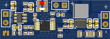
The Micro Powercore Charger (Manufacturer Part ID: Buck-Boost Power) is a compact and portable charging solution designed by Arduino. It is engineered to deliver efficient power to a variety of devices, making it ideal for on-the-go applications. With its integrated buck-boost converter, the charger ensures stable voltage output, even when the input voltage fluctuates. This makes it suitable for powering sensitive electronics, portable devices, and IoT systems.
Explore Projects Built with Micro Powercore Charger

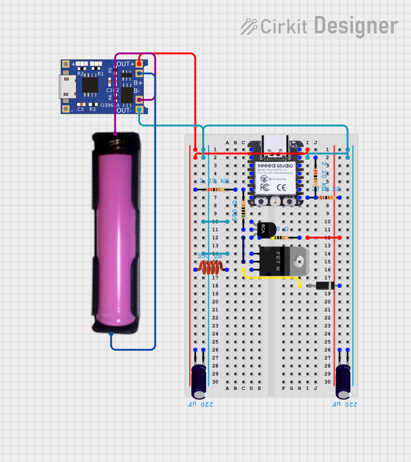
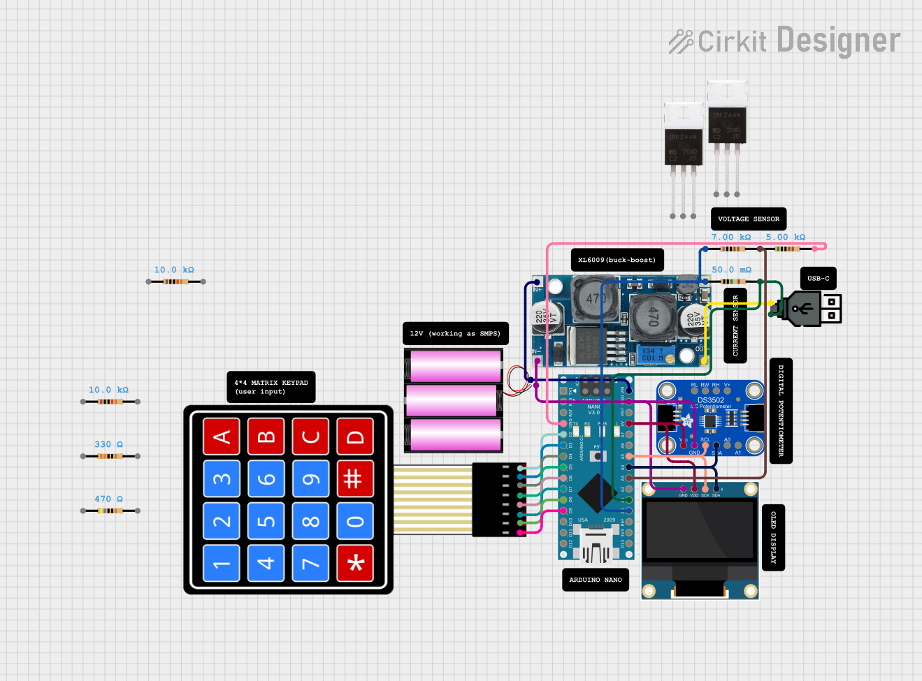

Explore Projects Built with Micro Powercore Charger
Common Applications and Use Cases
- Charging smartphones, tablets, and other portable devices
- Powering IoT devices and microcontroller-based projects
- Emergency backup power for small electronics
- Portable power supply for fieldwork or outdoor activities
Technical Specifications
The following table outlines the key technical details of the Micro Powercore Charger:
| Parameter | Value |
|---|---|
| Input Voltage Range | 3.0V to 12.0V |
| Output Voltage Range | 5.0V (fixed) |
| Output Current | Up to 2.4A |
| Efficiency | Up to 92% |
| Charging Ports | 2 USB-A ports, 1 USB-C port |
| Dimensions | 60mm x 40mm x 15mm |
| Weight | 50g |
| Operating Temperature | -10°C to 60°C |
| Protection Features | Overcurrent, overvoltage, short-circuit protection |
Pin Configuration and Descriptions
The Micro Powercore Charger features the following input and output connections:
| Pin/Port | Type | Description |
|---|---|---|
| USB-A Port 1 | Output | Standard USB-A port for charging devices (5V, up to 2.4A). |
| USB-A Port 2 | Output | Standard USB-A port for charging devices (5V, up to 2.4A). |
| USB-C Port | Input/Output | USB-C port for charging the power bank or powering devices (5V, up to 2.4A). |
| Micro-USB | Input | Micro-USB port for charging the power bank (5V, up to 2A). |
| LED Indicator | Status Output | Displays the battery level and charging status (4 LEDs for 25%, 50%, 75%, 100%). |
Usage Instructions
How to Use the Micro Powercore Charger
Charging the Powercore Charger:
- Connect a 5V power source (e.g., USB wall adapter) to the Micro-USB or USB-C input port.
- The LED indicators will light up sequentially to show the charging progress.
- When all four LEDs are lit, the charger is fully charged.
Powering Devices:
- Connect your device to one of the USB-A ports or the USB-C port using a compatible cable.
- The charger will automatically detect the connected device and begin supplying power.
Using with Arduino Projects:
- The Micro Powercore Charger can be used to power Arduino boards like the Arduino UNO.
- Connect the USB-A port to the Arduino UNO's USB input using a USB cable.
- Ensure the total current draw of your project does not exceed 2.4A.
Important Considerations and Best Practices
- Avoid exposing the charger to extreme temperatures or moisture.
- Do not exceed the maximum output current of 2.4A to prevent damage.
- Use high-quality cables to ensure efficient power delivery.
- When powering sensitive electronics, ensure the charger is fully charged to maintain stable output voltage.
Example: Powering an Arduino UNO
Here is an example of how to use the Micro Powercore Charger to power an Arduino UNO and control an LED:
// Example: Powering an Arduino UNO with the Micro Powercore Charger
// This code blinks an LED connected to pin 13 of the Arduino UNO.

// Define the LED pin
const int ledPin = 13;

void setup() {
  // Set the LED pin as an output
  pinMode(ledPin, OUTPUT);
}

void loop() {
  // Turn the LED on
  digitalWrite(ledPin, HIGH);
  delay(1000); // Wait for 1 second

  // Turn the LED off
  digitalWrite(ledPin, LOW);
  delay(1000); // Wait for 1 second
}
Troubleshooting and FAQs
Common Issues and Solutions
The charger is not powering my device:
- Ensure the device is compatible with a 5V power supply.
- Check the connection cable for damage or poor quality.
- Verify that the charger is not fully discharged (check the LED indicators).
The charger is not charging:
- Confirm that the input power source provides 5V and sufficient current (at least 2A).
- Try using a different charging cable or port.
- Inspect the Micro-USB or USB-C port for debris or damage.
The charger overheats during use:
- Ensure the total current draw does not exceed 2.4A.
- Avoid using the charger in high-temperature environments.
FAQs
Q: Can I use the Micro Powercore Charger to power multiple devices simultaneously?
A: Yes, you can connect multiple devices to the USB-A and USB-C ports, but ensure the total current draw does not exceed 2.4A.
Q: How long does it take to fully charge the Micro Powercore Charger?
A: Charging time depends on the input power source. Using a 5V/2A adapter, it typically takes 3-4 hours to fully charge.
Q: Is the charger safe to use with sensitive electronics?
A: Yes, the charger includes overcurrent, overvoltage, and short-circuit protection to ensure safe operation with sensitive devices.