How to Use OV2710 Camera: Examples, Pinouts, and Specs
Introduction
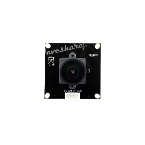
The OV2710 is a 2-megapixel image sensor designed for high-quality video and image capture. It is widely used in applications such as security cameras, webcams, automotive systems, and mobile devices. This component is known for its advanced image processing capabilities, excellent low-light performance, and support for multiple output formats, making it a versatile choice for both consumer and industrial applications.
Explore Projects Built with OV2710 Camera
Explore Projects Built with OV2710 Camera
Technical Specifications
The OV2710 offers a range of features that make it suitable for demanding imaging tasks. Below are its key technical specifications:
Key Specifications
- Resolution: 2 megapixels (1920 x 1080)
- Pixel Size: 3.0 µm x 3.0 µm
- Optical Format: 1/2.7 inch
- Frame Rate: Up to 30 fps at 1080p
- Dynamic Range: 69 dB
- Shutter Type: Rolling shutter
- Output Formats: RAW, YUV, RGB, and others
- Supply Voltage:
- Analog: 2.8V
- Digital: 1.8V
- I/O: 1.8V or 2.8V
- Operating Temperature: -30°C to 70°C
- Low-Light Sensitivity: Excellent performance in low-light conditions
Pin Configuration and Descriptions
The OV2710 sensor typically comes in a compact package with multiple pins for power, data, and control. Below is a table summarizing the pin configuration:
| Pin Name | Type | Description |
|---|---|---|
| VDD_A | Power | Analog power supply (2.8V) |
| VDD_D | Power | Digital core power supply (1.8V) |
| VDD_IO | Power | I/O power supply (1.8V or 2.8V) |
| GND | Ground | Ground connection |
| MCLK | Input | Master clock input |
| PCLK | Output | Pixel clock output |
| D[0:9] | Output | Data output pins (10-bit parallel data) |
| HSYNC | Output | Horizontal sync signal |
| VSYNC | Output | Vertical sync signal |
| SDA | Bidirectional | I2C data line for configuration |
| SCL | Input | I2C clock line for configuration |
| RESETB | Input | Active-low reset signal |
| PWDN | Input | Power-down mode control |
Usage Instructions
The OV2710 camera sensor can be integrated into a variety of systems. Below are the steps and considerations for using it effectively:
Connecting the OV2710 to a Circuit
- Power Supply: Ensure the sensor is powered with the correct voltages:
- Analog: 2.8V
- Digital: 1.8V
- I/O: 1.8V or 2.8V (depending on your system design)
- Clock Input: Provide a stable master clock (MCLK) signal, typically 24 MHz.
- I2C Configuration: Use the I2C interface (SDA and SCL pins) to configure the sensor's registers. This is necessary to set parameters such as resolution, frame rate, and output format.
- Data Output: Connect the data output pins (D[0:9]) to a compatible processor or FPGA for image data processing.
- Synchronization: Use the HSYNC and VSYNC signals for horizontal and vertical synchronization.
Important Considerations
- Lens Selection: Choose a lens compatible with the 1/2.7-inch optical format for optimal image quality.
- Low-Light Performance: Take advantage of the sensor's excellent low-light sensitivity for applications in dim environments.
- Heat Management: Ensure proper heat dissipation, especially in high-temperature environments, to maintain performance and reliability.
- I2C Configuration: Familiarize yourself with the sensor's register map to configure it for your specific application.
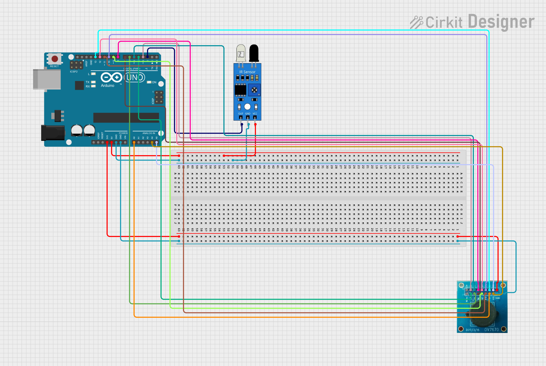
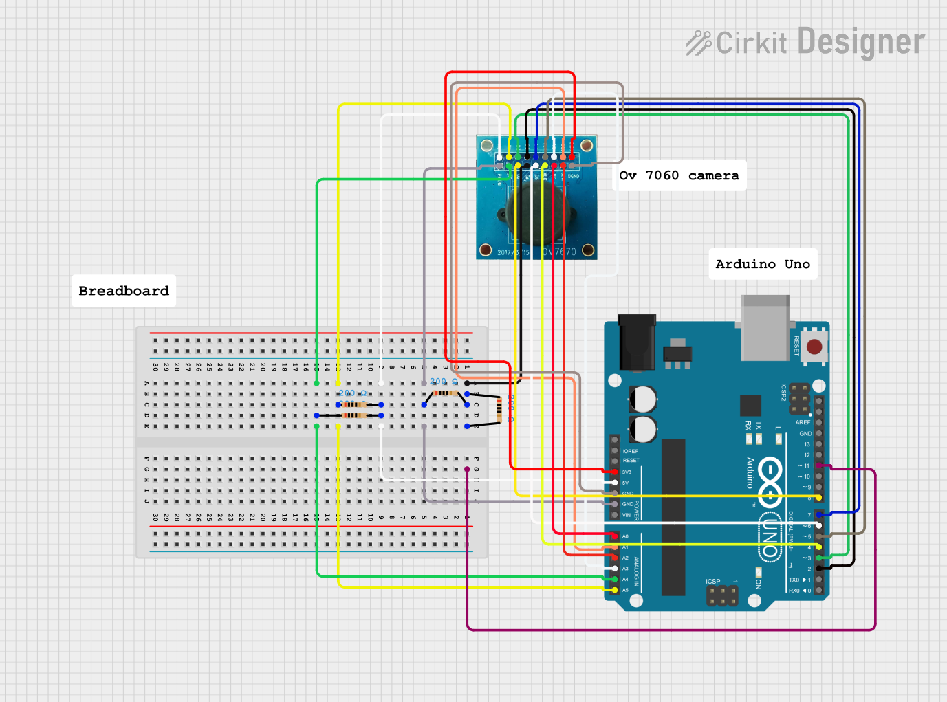
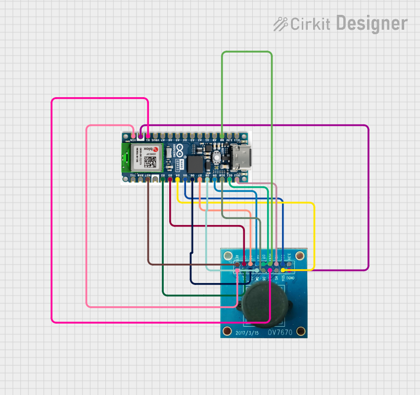
Example: Interfacing OV2710 with Arduino UNO
While the OV2710 is typically used with more powerful processors, it can be interfaced with an Arduino UNO for basic configuration and control via I2C. Below is an example code snippet:
#include <Wire.h> // Include the Wire library for I2C communication

#define OV2710_I2C_ADDRESS 0x36 // Replace with the actual I2C address of the sensor

void setup() {
  Wire.begin(); // Initialize I2C communication
  Serial.begin(9600); // Initialize serial communication for debugging

  // Reset the OV2710 sensor
  writeRegister(0x3008, 0x82); // Reset register (example address and value)
  delay(100); // Wait for the sensor to reset

  // Configure the sensor (example settings)
  writeRegister(0x3103, 0x11); // System clock from PLL
  writeRegister(0x3008, 0x02); // Power up the sensor

  Serial.println("OV2710 initialized.");
}

void loop() {
  // Main loop can be used to read data or adjust settings
}

// Function to write to a register on the OV2710
void writeRegister(uint16_t reg, uint8_t value) {
  Wire.beginTransmission(OV2710_I2C_ADDRESS);
  Wire.write((reg >> 8) & 0xFF); // Send the high byte of the register address
  Wire.write(reg & 0xFF);        // Send the low byte of the register address
  Wire.write(value);             // Send the value to write
  Wire.endTransmission();
}
Notes:
- The I2C address and register values in the example are placeholders. Refer to the OV2710 datasheet for the correct values.
- The Arduino UNO may not have sufficient processing power for real-time image processing but can be used for basic configuration and testing.
Troubleshooting and FAQs
Common Issues
No Image Output:
- Verify that the sensor is receiving the correct power supply voltages.
- Check the MCLK signal for stability and correct frequency.
- Ensure the I2C configuration is correct and matches your application requirements.
Poor Image Quality:
- Confirm that the lens is properly focused and clean.
- Adjust the sensor's exposure and gain settings via I2C.
I2C Communication Failure:
- Check the pull-up resistors on the SDA and SCL lines.
- Verify the I2C address of the sensor.
Overheating:
- Ensure proper ventilation and heat dissipation in your design.
Tips for Troubleshooting
- Use an oscilloscope or logic analyzer to monitor the I2C and clock signals.
- Refer to the OV2710 datasheet for detailed register descriptions and configuration examples.
- Test the sensor in a controlled environment before deploying it in the field.
By following this documentation, you can effectively integrate and use the OV2710 camera sensor in your projects.