How to Use Adafruit 1.2 Inch 8x8 LED Matrix Backpack Blue: Examples, Pinouts, and Specs
Introduction
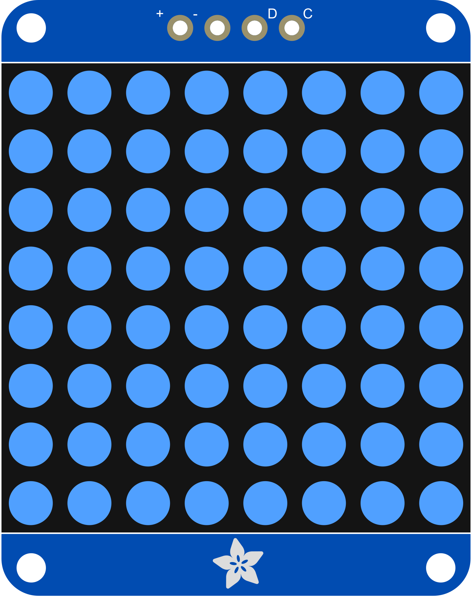
The Adafruit 1.2 Inch 8x8 LED Matrix Backpack Blue is a versatile and user-friendly electronic component designed for displaying characters, symbols, and animations. This LED matrix backpack is ideal for hobbyists and professionals looking to add a visual element to their projects. Common applications include creating digital signage, gaming displays, and interactive art installations.
Explore Projects Built with Adafruit 1.2 Inch 8x8 LED Matrix Backpack Blue
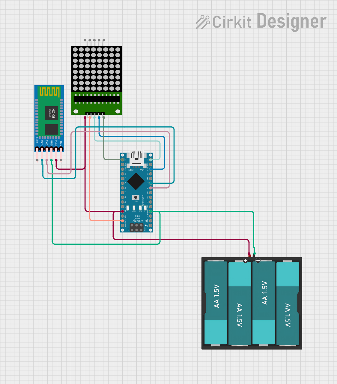

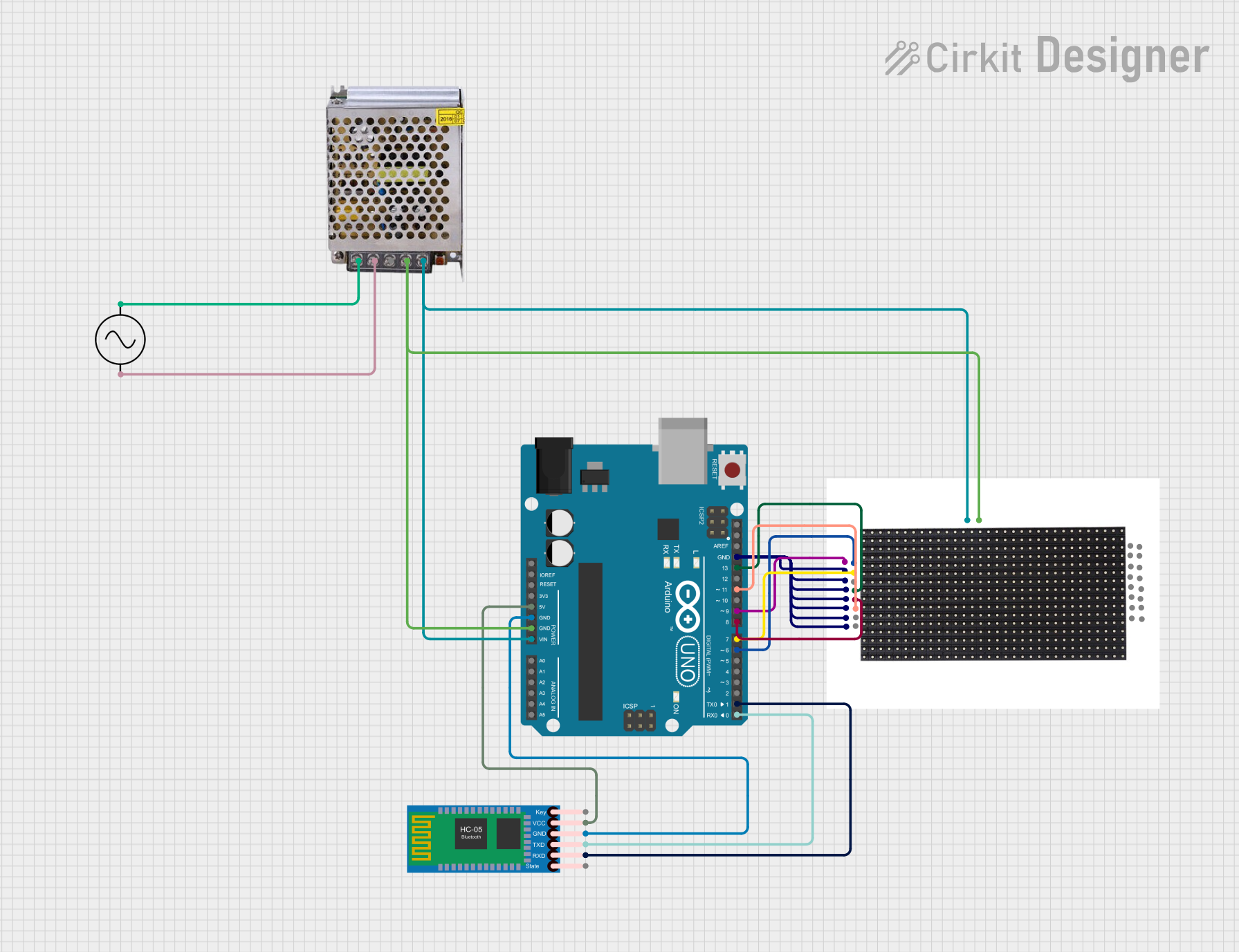

Explore Projects Built with Adafruit 1.2 Inch 8x8 LED Matrix Backpack Blue
Technical Specifications
Key Technical Details
- Display Color: Blue
- Matrix Size: 8x8 LEDs
- Dimensions: 1.2 inches (diagonal)
- Operating Voltage: 4.5V - 5.5V
- Max Current (per LED): 30mA
- Max Current (for all LEDs): 500mA
- Communication: I2C interface
Pin Configuration and Descriptions
| Pin Number | Name | Description |
|---|---|---|
| 1 | GND | Ground connection |
| 2 | VCC | Power supply (4.5V - 5.5V) |
| 3 | SDA | I2C Data line |
| 4 | SCL | I2C Clock line |
Usage Instructions
Interfacing with a Circuit
To use the Adafruit 1.2 Inch 8x8 LED Matrix Backpack Blue in your circuit, follow these steps:
- Connect the VCC pin to a 4.5V - 5.5V power supply.
- Connect the GND pin to the ground of your power supply.
- Interface the SDA and SCL pins with your microcontroller's I2C data and clock lines respectively.
Important Considerations and Best Practices
- Ensure that the power supply does not exceed 5.5V to prevent damage to the LED matrix.
- Use a current limiting resistor if necessary to prevent exceeding the maximum current rating per LED.
- When controlling multiple LED matrices, make sure to set unique I2C addresses for each one.
- Avoid looking directly at the LEDs when they are illuminated to prevent eye strain or damage.
Example Code for Arduino UNO
#include <Wire.h>
#include <Adafruit_GFX.h>
#include <Adafruit_LEDBackpack.h>

Adafruit_8x8matrix matrix = Adafruit_8x8matrix();

void setup() {
  matrix.begin(0x70); // Initialize the matrix with the I2C address
  matrix.setBrightness(10); // Set brightness level (0 is dim, 15 is bright)
}

void loop() {
  matrix.clear(); // Clear the matrix display
  matrix.drawPixel(4, 4, LED_ON); // Turn on a single LED at (x=4, y=4)
  matrix.writeDisplay(); // Update the display with the changes
  delay(500); // Wait for half a second
  matrix.clear(); // Clear the display again
  matrix.writeDisplay(); // Update the display
  delay(500); // Wait for half a second
}
This example initializes the LED matrix and blinks a single LED on and off. Make sure to include the Adafruit GFX and LED Backpack libraries in your Arduino IDE before uploading the code to your Arduino UNO.
Troubleshooting and FAQs
Common Issues
- LEDs not lighting up: Ensure that the power supply is correctly connected and within the specified voltage range. Check the I2C connections and address settings.
- Dim display: Adjust the brightness using the
setBrightnessfunction. Verify that the power supply can deliver sufficient current. - Garbled or incorrect display: Make sure the Adafruit GFX and LED Backpack libraries are correctly installed and imported in your code.
Solutions and Tips for Troubleshooting
- Double-check wiring connections for any loose or incorrect connections.
- Use the Arduino Serial Monitor to debug I2C communication issues.
- If using multiple LED matrices, ensure each one has a unique I2C address.
- Consult the Adafruit forums and community for additional support and resources.
FAQs
Q: Can I control each LED individually?
A: Yes, each LED can be controlled individually using the drawPixel function.
Q: How do I change the I2C address? A: The I2C address can be changed by soldering the address jumpers on the back of the PCB. Refer to the Adafruit guide for detailed instructions.
Q: Is it possible to daisy-chain multiple matrices? A: Yes, you can daisy-chain multiple matrices by connecting their I2C lines in parallel and assigning unique addresses to each matrix.
Q: Can this LED matrix display colors other than blue? A: This specific model only displays blue, but other models with different colored LEDs are available.
For further assistance, refer to the Adafruit support forums or contact technical support.