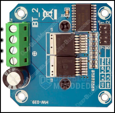
The BTS7960 is a high-current H-bridge motor driver designed for driving DC motors and other inductive loads. Manufactured by an unknown Chinese manufacturer under the part ID "motorcontroller," this component is widely used in robotics, automation, and other applications requiring precise motor control. It supports bidirectional motor control and features built-in protection mechanisms, including overcurrent, overtemperature, and undervoltage protection, ensuring reliable operation in demanding environments.
Explore Projects Built with BTS7960
Use Cirkit Designer to design, explore, and prototype these projects online. Some projects support real-time simulation. Click "Open Project" to start designing instantly!
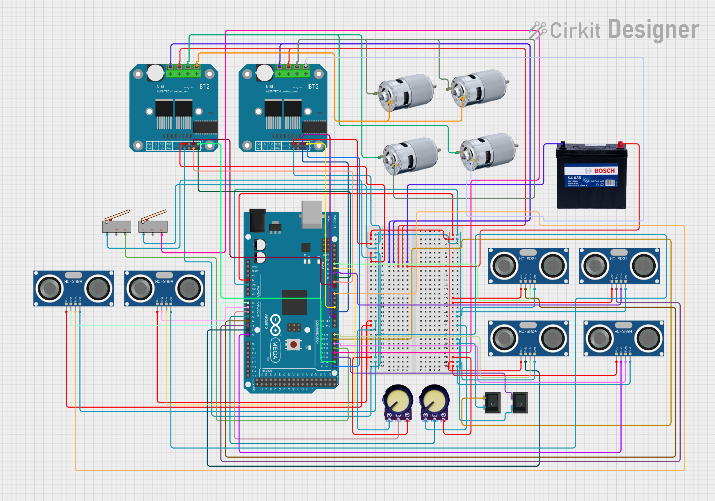
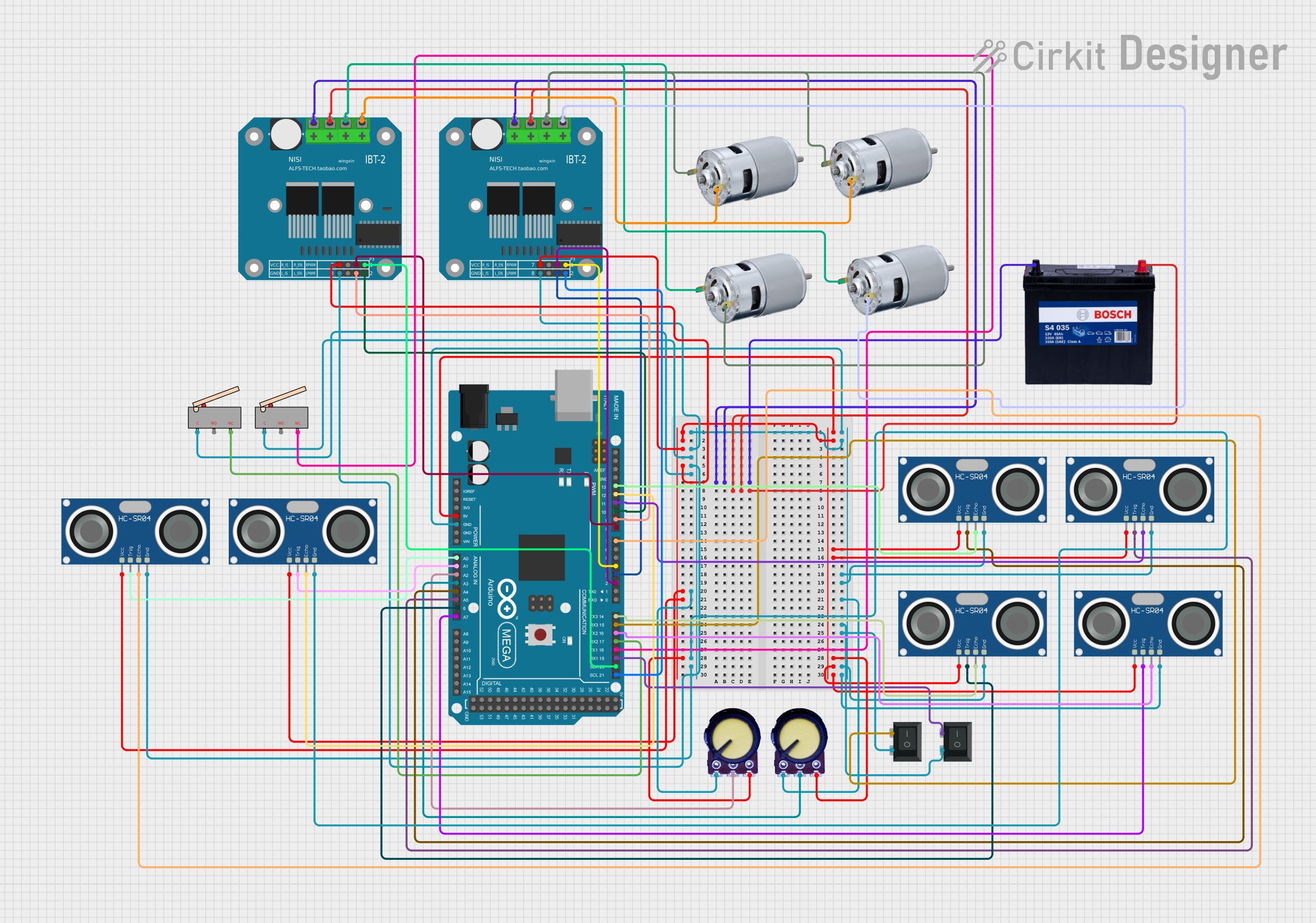
This circuit is a robotic control system utilizing an Arduino Mega 2560 to manage two BTS7960 motor drivers for controlling multiple 775 motors. It incorporates several HC-SR04 ultrasonic sensors for obstacle detection, potentiometers for setting movement limits, and limit switches for safety, enabling the robot to navigate and avoid obstacles autonomously.
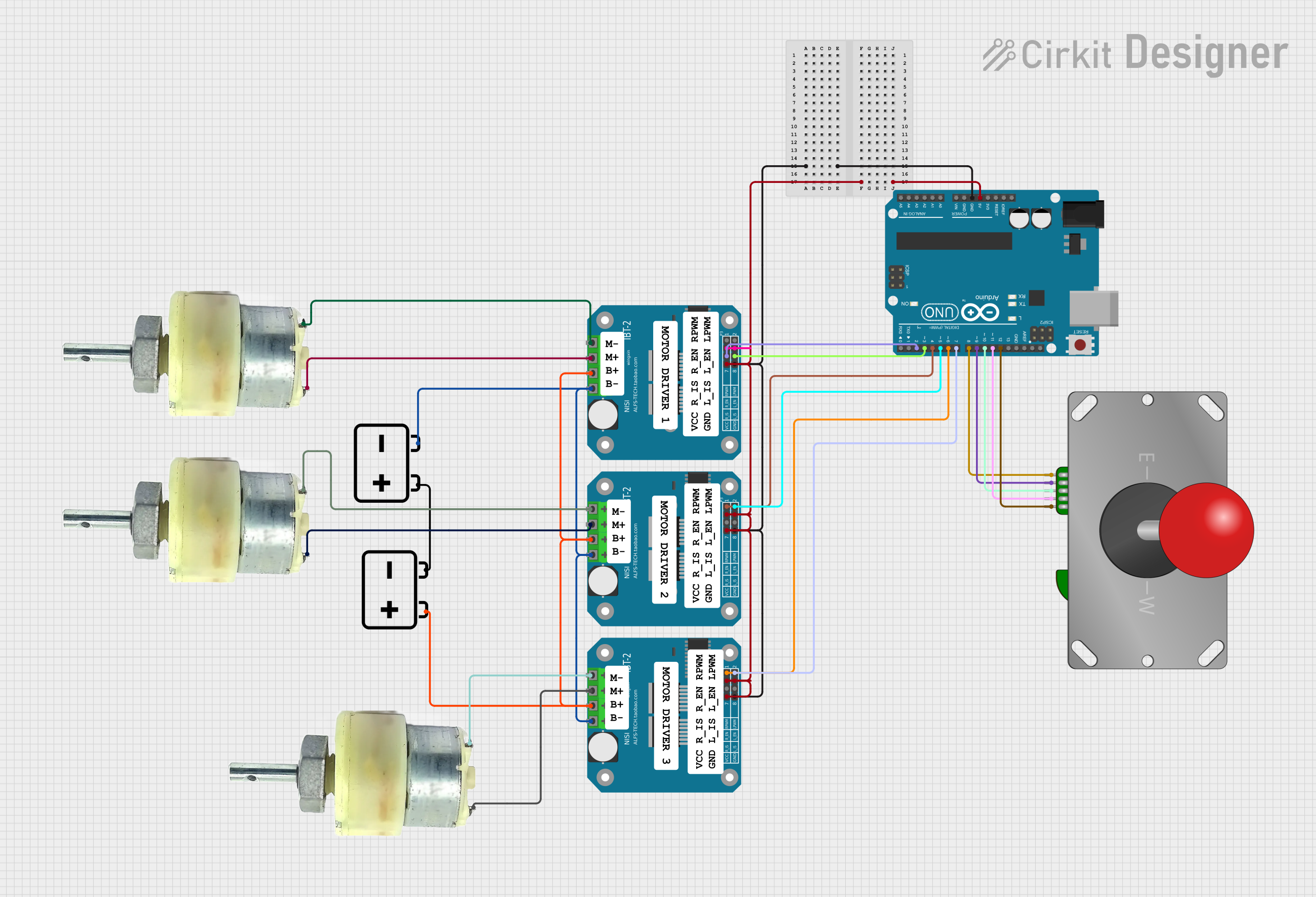
This is a joystick-controlled motor driving system. An Arduino UNO reads inputs from an Adafruit Arcade Joystick and outputs control signals to BTS7960 motor drivers, which in turn power several 12V geared motors. The system is designed for directional control of motors, suitable for applications such as robotic vehicles or motorized platforms.
This circuit is a robotic system controlled by an Arduino Mega 2560, which uses multiple ultrasonic sensors for obstacle detection and potentiometers for setting movement limits. It drives four 775 motors through two BTS7960 motor drivers, with limit switches and a rocker switch for additional control inputs.
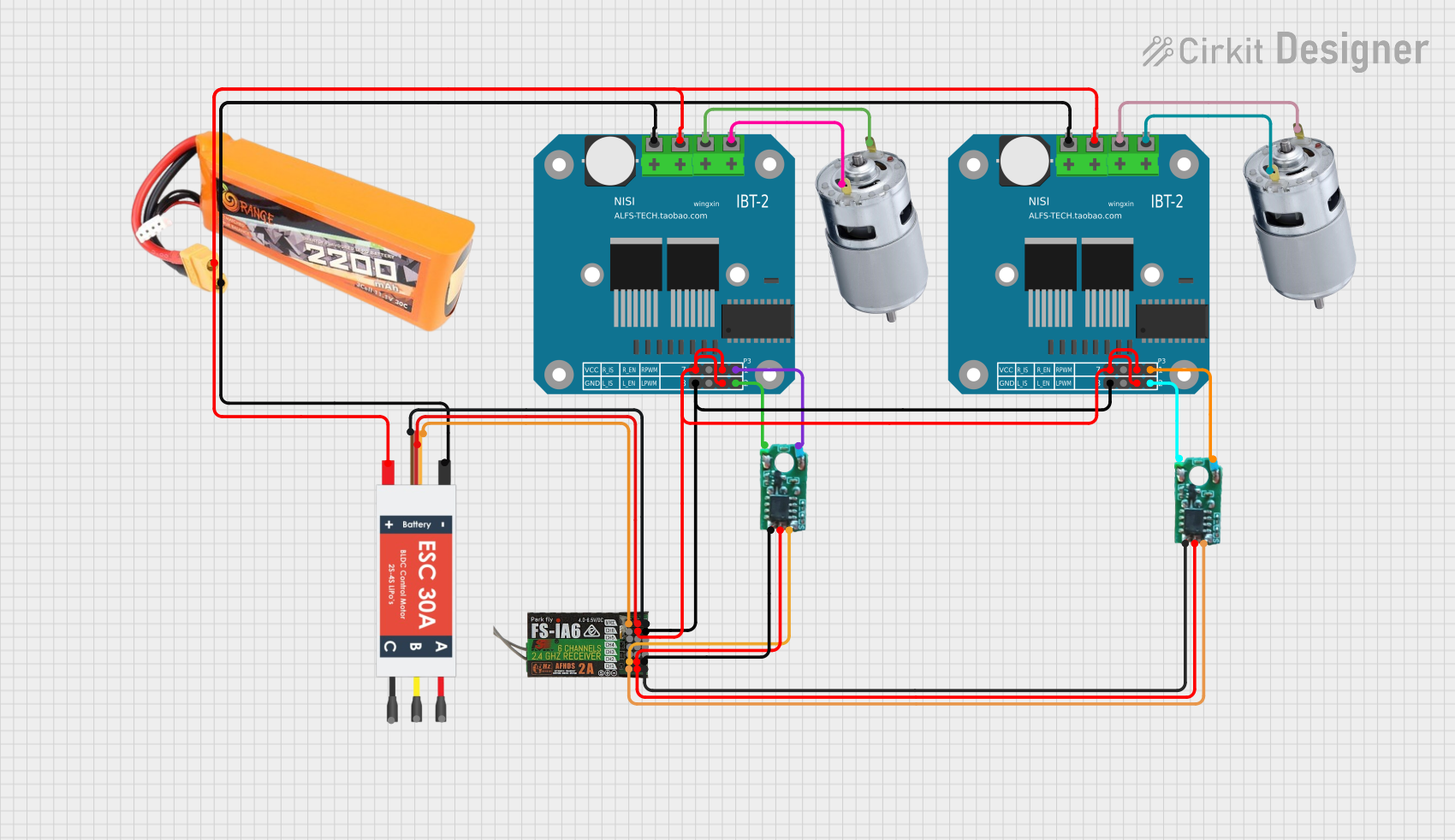
This circuit is designed to control two 775 motors using BTS7960 motor drivers, an electronic speed controller (ESC), and a Fly Sky receiver. The Fly Sky receiver receives control signals and distributes them to the motor drivers and servo internal circuits, which in turn control the motors. Power is supplied by a 2200mAh LiPo battery.
The BTS7960 is a robust motor driver with the following key specifications:
Parameter
Value
Operating Voltage (Vcc)
5V (logic level)
Motor Voltage (VM)
6V to 27V
Continuous Output Current
Up to 43A
Peak Output Current
50A
PWM Frequency
Up to 25kHz
Logic Input Voltage
3.3V to 5V
Overcurrent Protection
Yes
Overtemperature Protection
Yes
Undervoltage Protection
Yes
Pin Configuration
The BTS7960 module typically comes with a 12-pin interface. Below is the pinout and description:
Pin Name
Type
Description
VCC
Power Input
5V logic power supply input.
GND
Power Input
Ground connection for logic and motor power.
RPWM
Logic Input
PWM signal input for controlling motor speed in one direction.
LPWM
Logic Input
PWM signal input for controlling motor speed in the opposite direction.
R_EN
Logic Input
Enable pin for the right side of the H-bridge. Active HIGH.
L_EN
Logic Input
Enable pin for the left side of the H-bridge. Active HIGH.
R_IS
Analog Output
Current sense output for the right side of the H-bridge.
L_IS
Analog Output
Current sense output for the left side of the H-bridge.
VM+
Power Input
Positive terminal for motor power supply (6V to 27V).
VM-
Power Input
Negative terminal for motor power supply (connected to GND).
MOTOR+
Power Output
Positive terminal for the motor connection.
MOTOR-
Power Output
Negative terminal for the motor connection.
Usage Instructions
Connecting the BTS7960 to a Circuit
Power Supply: Connect a 6V to 27V power source to the VM+ and VM- pins. Ensure the power supply can handle the motor's current requirements.
Logic Power: Provide a 5V logic power supply to the VCC pin and connect the GND pin to the ground of your microcontroller.
Motor Connection: Connect the motor terminals to the MOTOR+ and MOTOR- pins.
Control Signals: Use the RPWM and LPWM pins to send PWM signals for speed control. Use the R_EN and L_EN pins to enable or disable the respective sides of the H-bridge.
Example: Using BTS7960 with Arduino UNO
Below is an example Arduino sketch to control a motor using the BTS7960:
// Define control pins for the BTS7960
#define RPWM 9  // PWM pin for forward direction
#define LPWM 10 // PWM pin for reverse direction
#define R_EN 8  // Enable pin for forward direction
#define L_EN 7  // Enable pin for reverse direction

void setup() {
  // Set control pins as outputs
  pinMode(RPWM, OUTPUT);
  pinMode(LPWM, OUTPUT);
  pinMode(R_EN, OUTPUT);
  pinMode(L_EN, OUTPUT);

  // Enable both sides of the H-bridge
  digitalWrite(R_EN, HIGH);
  digitalWrite(L_EN, HIGH);
}

void loop() {
  // Example: Run motor forward at 50% speed
  analogWrite(RPWM, 128); // 50% duty cycle (128 out of 255)
  analogWrite(LPWM, 0);   // No reverse signal
  delay(2000);            // Run for 2 seconds

  // Example: Run motor in reverse at 75% speed
  analogWrite(RPWM, 0);   // No forward signal
  analogWrite(LPWM, 192); // 75% duty cycle (192 out of 255)
  delay(2000);            // Run for 2 seconds

  // Stop the motor
  analogWrite(RPWM, 0);
  analogWrite(LPWM, 0);
  delay(2000);            // Wait for 2 seconds
}
Important Considerations
Heat Dissipation: The BTS7960 can handle high currents, but it may generate significant heat. Use a heatsink or active cooling if necessary.
Power Supply: Ensure the motor power supply can provide sufficient current for the motor's operation.
PWM Frequency: Use a PWM frequency within the recommended range (up to 25kHz) for optimal performance.
Protection Features: The built-in protection mechanisms are helpful, but avoid pushing the module to its absolute limits to ensure longevity.
Troubleshooting and FAQs
Common Issues
Motor Not Running
Cause: Incorrect wiring or insufficient power supply.
Solution: Double-check all connections and ensure the power supply meets the motor's requirements.
Overheating
Cause: Prolonged operation at high currents without proper cooling.
Solution: Add a heatsink or active cooling to the module.
Erratic Motor Behavior
Cause: Noise in the PWM signal or insufficient grounding.
Solution: Use proper decoupling capacitors and ensure a solid ground connection.
No Response to PWM Signals
Cause: Incorrect logic voltage levels or damaged module.
Solution: Verify the logic voltage is 5V and test the module with a known working setup.
FAQs
Q: Can the BTS7960 drive stepper motors?
A: No, the BTS7960 is designed for DC motors and other inductive loads. Stepper motors require a dedicated stepper driver.
Q: What is the maximum motor voltage the BTS7960 can handle?
A: The BTS7960 supports motor voltages from 6V to 27V.
Q: Can I use the BTS7960 with a 3.3V microcontroller?
A: Yes, the logic input pins are compatible with both 3.3V and 5V signals.
Q: How do I know if the module's protection features are active?
A: The module will automatically shut down or limit current when protection features are triggered. Check your circuit for faults if this occurs frequently.

 Open Project in Cirkit Designer