Cirkit Designer
Your all-in-one circuit design IDE
Home /
Component Documentation
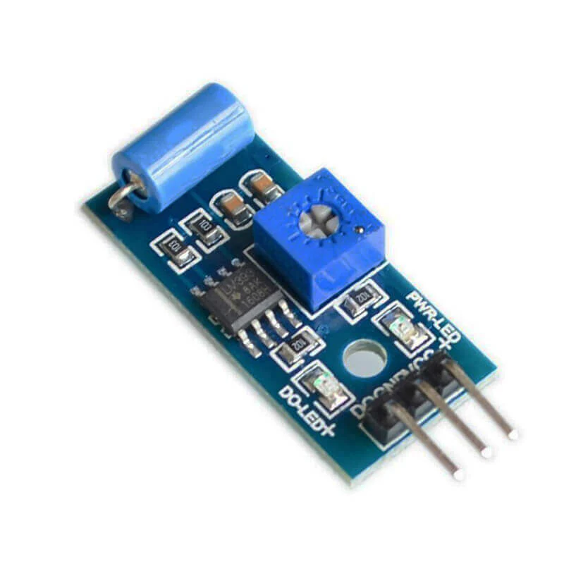
How to Use vibrational_sensor: Examples, Pinouts, and Specs
Introduction
A vibrational sensor is a device designed to detect and measure vibrations or oscillations in a system. These sensors are commonly used in various applications, including:
- Monitoring machinery health and performance
- Structural health monitoring in buildings and bridges
- Automotive applications for detecting engine vibrations
- Consumer electronics for motion detection
- Industrial equipment monitoring
Vibrational sensors help in predictive maintenance by identifying potential issues before they lead to system failures, thereby reducing downtime and maintenance costs.
Explore Projects Built with vibrational_sensor
Arduino Nano-Based Wearable Gesture Control Interface with Bluetooth Connectivity

This is a battery-powered sensor system with Bluetooth communication, featuring an Arduino Nano for control, an MPU-6050 for motion sensing, and an HC-05 module for wireless data transmission. It includes a vibration motor for haptic feedback, a flex resistor as an additional sensor, and a piezo speaker and LED for alerts or status indication.
Arduino Nano-Based Haptic Navigation Shoe for the Visually Impaired with Bluetooth Connectivity
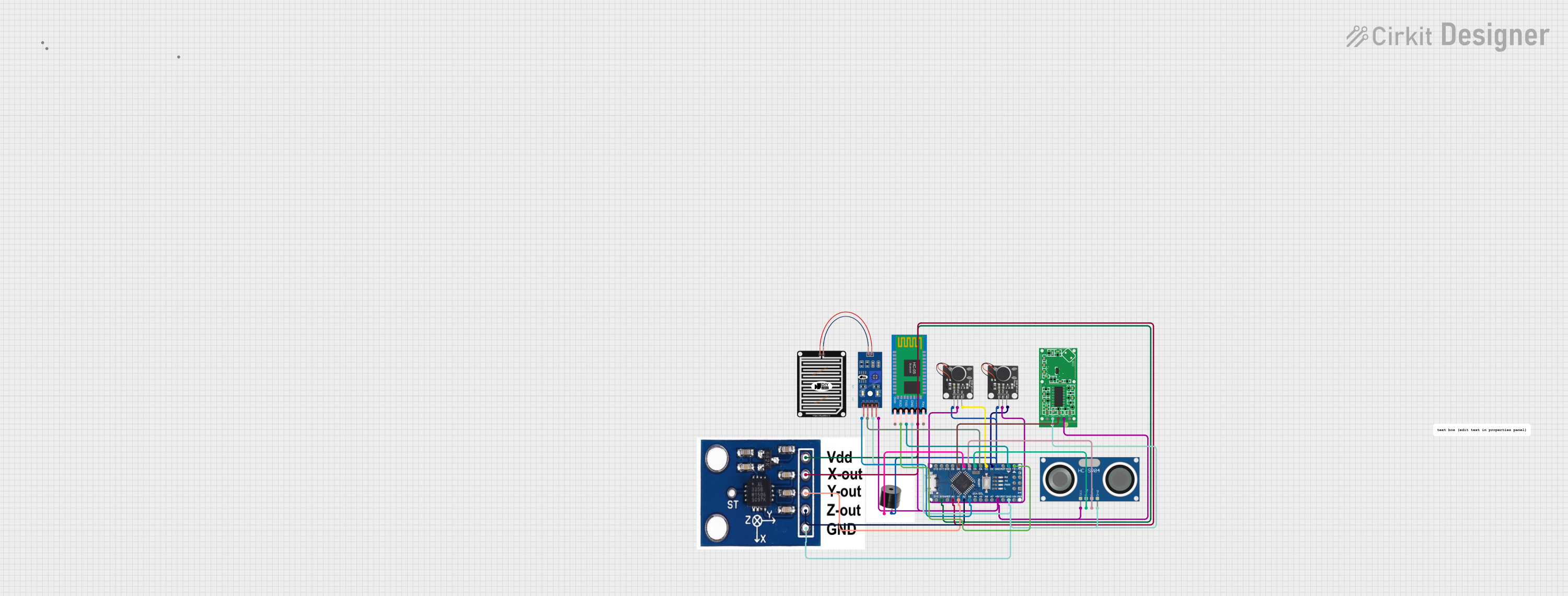
This circuit is a haptic navigation system for the visually impaired, utilizing an Arduino Nano to interface with various sensors including a rain sensor, ultrasonic sensor, accelerometer, radar sensor, and Bluetooth module. The system provides feedback through vibration motors and a buzzer, and sends sensor data to a mobile app via Bluetooth for tracking and alerts.
ESP32-Based Smart Environmental Monitoring System with Battery Power
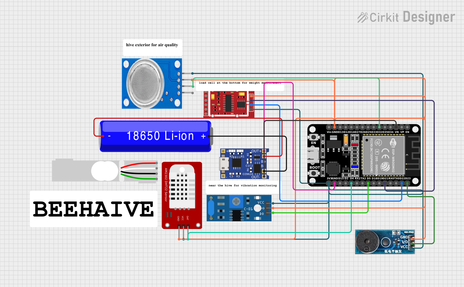
This circuit is a multi-sensor monitoring system powered by an ESP32 microcontroller. It includes sensors for gas (MQ135), vibration (SW-420), weight (HX711 with a load cell), and temperature/humidity (DHT22), along with a buzzer for alerts. The system is powered by a 18650 Li-ion battery managed by a TP4056 charging module.
Arduino UNO-Based Multi-Sensor Security System with PIR, Gas, and Vibration Detection
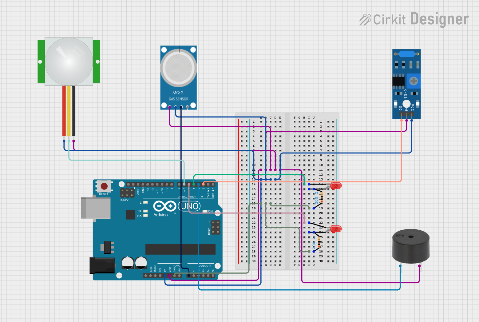
This circuit is a multi-sensor monitoring system using an Arduino UNO, which integrates a PIR sensor, an MQ-2 gas sensor, and an SW-420 vibration sensor. The system uses LEDs and a buzzer to provide visual and auditory alerts based on sensor inputs.
Explore Projects Built with vibrational_sensor
Arduino Nano-Based Wearable Gesture Control Interface with Bluetooth Connectivity
This is a battery-powered sensor system with Bluetooth communication, featuring an Arduino Nano for control, an MPU-6050 for motion sensing, and an HC-05 module for wireless data transmission. It includes a vibration motor for haptic feedback, a flex resistor as an additional sensor, and a piezo speaker and LED for alerts or status indication.
Arduino Nano-Based Haptic Navigation Shoe for the Visually Impaired with Bluetooth Connectivity
This circuit is a haptic navigation system for the visually impaired, utilizing an Arduino Nano to interface with various sensors including a rain sensor, ultrasonic sensor, accelerometer, radar sensor, and Bluetooth module. The system provides feedback through vibration motors and a buzzer, and sends sensor data to a mobile app via Bluetooth for tracking and alerts.
ESP32-Based Smart Environmental Monitoring System with Battery Power
This circuit is a multi-sensor monitoring system powered by an ESP32 microcontroller. It includes sensors for gas (MQ135), vibration (SW-420), weight (HX711 with a load cell), and temperature/humidity (DHT22), along with a buzzer for alerts. The system is powered by a 18650 Li-ion battery managed by a TP4056 charging module.
Arduino UNO-Based Multi-Sensor Security System with PIR, Gas, and Vibration Detection
This circuit is a multi-sensor monitoring system using an Arduino UNO, which integrates a PIR sensor, an MQ-2 gas sensor, and an SW-420 vibration sensor. The system uses LEDs and a buzzer to provide visual and auditory alerts based on sensor inputs.
Technical Specifications
Key Technical Details
| Parameter | Value |
|---|---|
| Operating Voltage | 3.3V to 5V |
| Operating Current | < 10mA |
| Sensitivity | Adjustable via potentiometer |
| Output Type | Digital (High/Low) |
| Response Time | < 1ms |
| Operating Temperature | -20°C to 70°C |
Pin Configuration and Descriptions
| Pin Number | Pin Name | Description |
|---|---|---|
| 1 | VCC | Power supply (3.3V to 5V) |
| 2 | GND | Ground |
| 3 | OUT | Digital output signal (High/Low) |
| 4 | ADJ | Sensitivity adjustment (potentiometer) |
Usage Instructions
How to Use the Component in a Circuit
- Power Supply: Connect the VCC pin to a 3.3V or 5V power supply and the GND pin to the ground of your circuit.
- Output Signal: Connect the OUT pin to a digital input pin on your microcontroller (e.g., Arduino UNO).
- Sensitivity Adjustment: Use the potentiometer (ADJ pin) to adjust the sensitivity of the sensor. Turning the potentiometer clockwise increases sensitivity, while turning it counterclockwise decreases sensitivity.
Important Considerations and Best Practices
- Power Supply: Ensure that the power supply voltage is within the specified range (3.3V to 5V) to avoid damaging the sensor.
- Mounting: Securely mount the sensor to the surface where vibrations are to be measured. Loose mounting can result in inaccurate readings.
- Noise Reduction: Use proper shielding and grounding techniques to minimize electrical noise and interference.
- Calibration: Periodically calibrate the sensor to maintain accuracy, especially in environments with varying temperature and humidity.
Example Code for Arduino UNO
// Vibrational Sensor Example Code for Arduino UNO

const int sensorPin = 2; // Pin connected to the sensor's OUT pin
const int ledPin = 13;   // Pin connected to the onboard LED

void setup() {
  pinMode(sensorPin, INPUT); // Set sensor pin as input
  pinMode(ledPin, OUTPUT);   // Set LED pin as output
  Serial.begin(9600);        // Initialize serial communication
}

void loop() {
  int sensorValue = digitalRead(sensorPin); // Read the sensor value

  if (sensorValue == HIGH) {
    digitalWrite(ledPin, HIGH); // Turn on the LED if vibration is detected
    Serial.println("Vibration detected!");
  } else {
    digitalWrite(ledPin, LOW);  // Turn off the LED if no vibration
  }

  delay(100); // Small delay to avoid serial flooding
}
Troubleshooting and FAQs
Common Issues Users Might Face
No Output Signal:
- Solution: Check the power supply connections and ensure the sensor is properly powered. Verify that the sensor is securely mounted and the sensitivity is correctly adjusted.
False Triggers:
- Solution: Reduce the sensitivity using the potentiometer. Ensure that the sensor is not exposed to excessive electrical noise or interference.
Inconsistent Readings:
- Solution: Ensure the sensor is firmly mounted. Check for loose connections and ensure proper grounding. Calibrate the sensor if necessary.
FAQs
Q1: Can the vibrational sensor detect very small vibrations?
- A1: Yes, the sensitivity of the sensor can be adjusted using the potentiometer to detect small vibrations.
Q2: Can I use the vibrational sensor with a 3.3V microcontroller?
- A2: Yes, the sensor operates within a voltage range of 3.3V to 5V, making it compatible with 3.3V microcontrollers.
Q3: How do I know if the sensor is working correctly?
- A3: You can test the sensor by connecting it to an LED or a microcontroller. When vibrations are detected, the sensor's output pin will go HIGH, turning on the LED or triggering a response in the microcontroller.
By following this documentation, users can effectively integrate and utilize the vibrational sensor in their projects, ensuring accurate and reliable vibration detection.