How to Use Adafruit Feather M0 Basic Proto: Examples, Pinouts, and Specs
Introduction
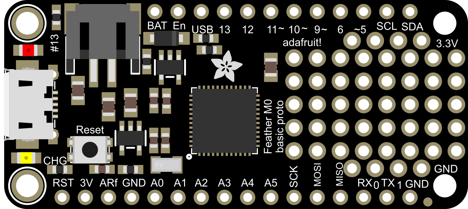
The Adafruit Feather M0 Basic Proto is a versatile and compact development board that serves as a great starting point for building electronic projects and prototypes. Based on the powerful ATSAMD21G18 ARM Cortex M0 microcontroller, it offers a balance between performance and power consumption. This board is part of the Feather ecosystem, designed by Adafruit to be a new standard for portable microcontroller cores.
Explore Projects Built with Adafruit Feather M0 Basic Proto

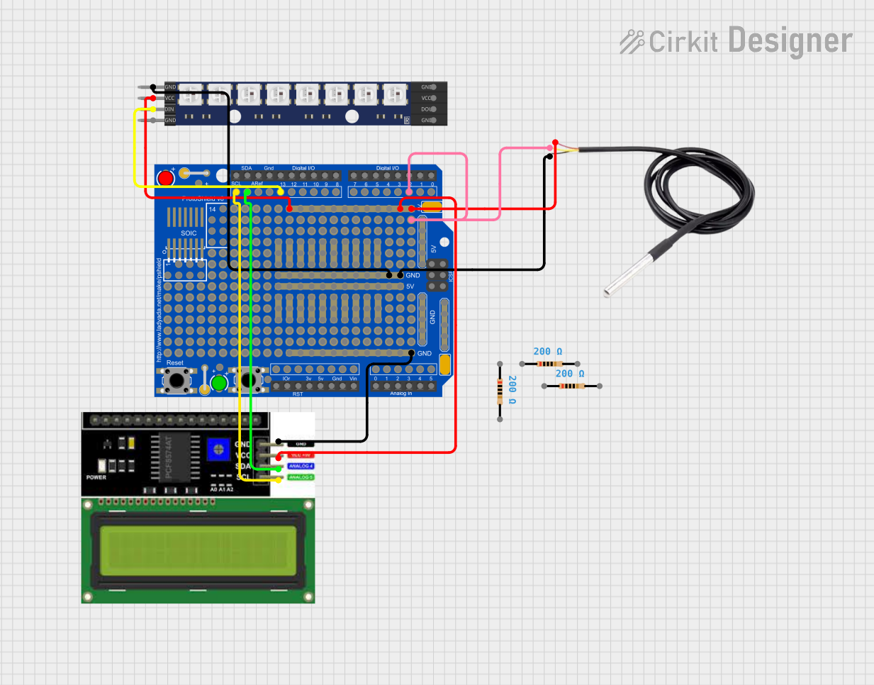
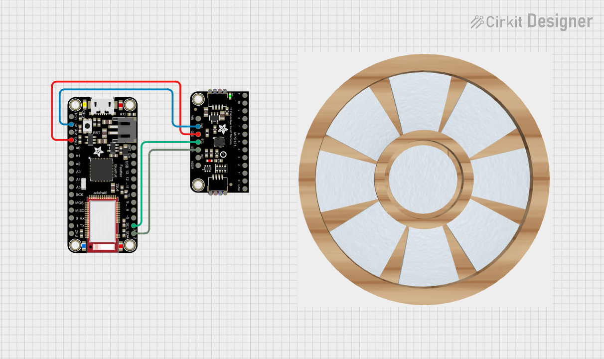
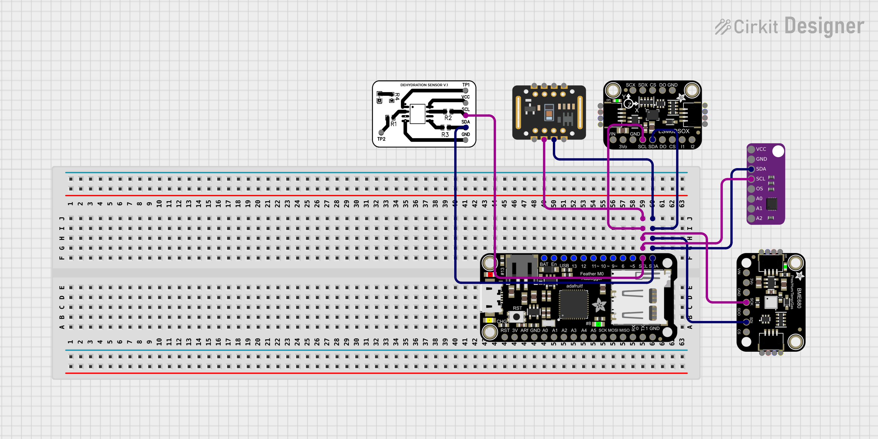
Explore Projects Built with Adafruit Feather M0 Basic Proto
Common Applications and Use Cases
- Wearable electronics
- Portable projects
- Educational purposes
- Prototyping IoT devices
- DIY electronics
Technical Specifications
Key Technical Details
- Microcontroller: ATSAMD21G18, 32-bit ARM Cortex M0+
- Operating Voltage: 3.3V
- Input Voltage: 3.7-6V via battery and up to 12V via the USB pin
- Digital I/O Pins: 20
- PWM Channels: 12
- Analog Input Channels: 10 (12-bit ADC)
- Analog Output Channels: 1 (10-bit DAC)
- Flash Memory: 256KB
- SRAM: 32KB
- Clock Speed: 48 MHz
- Dimensions: 51mm x 23mm x 8mm (without headers)
Pin Configuration and Descriptions
| Pin Number | Function | Description |
|---|---|---|
| 1 | GND | Ground |
| 2 | BAT | Battery +3.7V to +6V input |
| 3 | EN | Enable pin for the 3.3V regulator |
| 4 | USB | USB pin, can be up to +12V |
| 5-14 | Digital Pins | Digital input/output pins, PWM capable |
| 15-24 | Analog Pins | Analog input pins, also digital I/O capable |
| 25 | AREF | Analog reference voltage for the ADC |
| 26 | SCK | SPI clock |
| 27 | MISO | SPI Master In Slave Out |
| 28 | MOSI | SPI Master Out Slave In |
| 29 | RX | UART receive pin |
| 30 | TX | UART transmit pin |
| 31 | SDA | I2C data line |
| 32 | SCL | I2C clock line |
| 33 | RST | Reset pin |
Usage Instructions
How to Use the Component in a Circuit
- Powering the Board: Connect a battery to the BAT pin or supply power through the USB pin.
- Programming: Use the micro USB port to connect the Feather M0 to your computer for programming.
- Digital I/O: Utilize the digital pins for input or output functions. They can be used with digital sensors, LEDs, buttons, etc.
- Analog Input: Connect analog sensors to the analog pins to read varying voltages.
- PWM Output: Use PWM-capable pins to control motors, dim LEDs, etc.
- Serial Communication: Utilize RX and TX for UART communication.
- SPI/I2C: Use the dedicated pins for SPI or I2C communication with peripherals.
Important Considerations and Best Practices
- Always ensure that the power supply voltage is within the specified range to prevent damage.
- When using PWM, remember that the resolution is limited to the capabilities of the microcontroller.
- For analog readings, ensure that the input voltage does not exceed 3.3V.
- Use the prototyping area to add components and build your circuit directly on the board.
- Avoid applying force to the board when inserting or removing it from a breadboard to prevent bending the pins.
Troubleshooting and FAQs
Common Issues
- Board not recognized by computer: Ensure the micro USB cable is data-capable and the board's drivers are installed.
- Inconsistent analog readings: Check for proper grounding and stable power supply.
- Unable to upload sketches: Verify the correct board and port are selected in your IDE.
Solutions and Tips for Troubleshooting
- If the board is not recognized, try a different USB cable or port, and reset the board.
- For analog issues, add a small capacitor between the analog pin and ground to filter noise.
- Ensure that no other program is using the selected port when uploading sketches.
FAQs
Q: Can I power the Feather M0 Basic Proto with a LiPo battery? A: Yes, you can connect a 3.7V LiPo battery to the JST connector.
Q: Is the Feather M0 Basic Proto compatible with Arduino IDE? A: Yes, it is compatible with the Arduino IDE. You'll need to install the Adafruit SAMD board package.
Q: What is the maximum current the I/O pins can source or sink? A: Each I/O pin can source or sink up to 7 mA.
Q: Can I use the Feather M0 Basic Proto with other FeatherWings? A: Yes, the Feather M0 Basic Proto is designed to be stackable with other FeatherWings.
Example Code for Arduino UNO
Here is a simple example of blinking an LED connected to pin 13 of the Feather M0 Basic Proto using the Arduino IDE:
// Define the LED pin
const int ledPin = 13;

// the setup routine runs once when you press reset:
void setup() {
  // initialize the digital pin as an output.
  pinMode(ledPin, OUTPUT);
}

// the loop routine runs over and over again forever:
void loop() {
  digitalWrite(ledPin, HIGH);   // turn the LED on (HIGH is the voltage level)
  delay(1000);                  // wait for a second
  digitalWrite(ledPin, LOW);    // turn the LED off by making the voltage LOW
  delay(1000);                  // wait for a second
}
Remember to select the correct board from the Tools > Board menu in the Arduino IDE before uploading the code to the Feather M0 Basic Proto.