
How to Use Pushbutton: Examples, Pinouts, and Specs
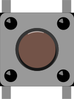
 Design with Pushbutton in Cirkit Designer
Introduction
A pushbutton is a momentary switch that completes a circuit when pressed and breaks the circuit when released. It is a simple yet essential component in electronics, commonly used for user input in devices such as calculators, remote controls, and microcontroller-based projects. Pushbuttons are available in various sizes and designs, making them versatile for a wide range of applications.
Explore Projects Built with Pushbutton
 Open Project in Cirkit Designer
 Open Project in Cirkit Designer
 Open Project in Cirkit Designer
 Open Project in Cirkit Designer
Explore Projects Built with Pushbutton
Open Project in Cirkit DesignerOpen Project in Cirkit DesignerOpen Project in Cirkit DesignerOpen Project in Cirkit DesignerCommon Applications and Use Cases
- User input for microcontroller projects (e.g., Arduino, Raspberry Pi)
- Reset or power buttons in electronic devices
- Control panels for appliances and machinery
- Prototyping and testing circuits
- Interactive projects such as games or toys
Technical Specifications
Below are the general technical specifications for a standard pushbutton:
| Parameter | Value |
|---|---|
| Operating Voltage | 3.3V to 12V (typical) |
| Maximum Current Rating | 50mA to 500mA (depending on type) |
| Contact Resistance | < 100 mΩ |
| Insulation Resistance | > 100 MΩ |
| Operating Temperature | -20°C to +70°C |
| Mechanical Lifespan | 100,000 to 1,000,000 presses |
Pin Configuration and Descriptions
A standard 4-pin pushbutton typically has the following pin configuration:
| Pin Number | Description |
|---|---|
| Pin 1 | Connected to one side of the switch |
| Pin 2 | Connected to the same side as Pin 1 |
| Pin 3 | Connected to the other side of the switch |
| Pin 4 | Connected to the same side as Pin 3 |
Note: Pins 1 and 2 are internally connected, as are Pins 3 and 4. This allows the pushbutton to be used in either orientation.
Usage Instructions
How to Use the Pushbutton in a Circuit
Connect the Pushbutton:
- Identify the two pairs of internally connected pins (Pins 1 & 2, and Pins 3 & 4).
- Connect one pair to the input signal or power source.
- Connect the other pair to the load or microcontroller input pin.
Use a Pull-Up or Pull-Down Resistor:
- Pushbuttons do not inherently provide a stable HIGH or LOW signal. Use a pull-up resistor (to VCC) or a pull-down resistor (to GND) to ensure a stable signal when the button is not pressed.
Debounce the Signal:
- Mechanical pushbuttons can produce noise or "bouncing" when pressed or released. Use a capacitor or software debounce logic to filter out these unwanted signals.
Example Circuit with Arduino UNO
Below is an example of how to connect a pushbutton to an Arduino UNO and read its state:
Circuit Connections:
- Connect one side of the pushbutton (Pins 1 & 2) to digital pin 2 on the Arduino.
- Connect the other side of the pushbutton (Pins 3 & 4) to GND.
- Add a 10kΩ pull-up resistor between digital pin 2 and VCC.
Arduino Code:
// Define the pin connected to the pushbutton
const int buttonPin = 2;

// Variable to store the button state
int buttonState = 0;

void setup() {
  // Set the button pin as an input
  pinMode(buttonPin, INPUT);

  // Initialize serial communication for debugging
  Serial.begin(9600);
}

void loop() {
  // Read the state of the pushbutton
  buttonState = digitalRead(buttonPin);

  // Print the button state to the Serial Monitor
  if (buttonState == HIGH) {
    Serial.println("Button Pressed");
  } else {
    Serial.println("Button Released");
  }

  // Add a small delay to avoid spamming the Serial Monitor
  delay(100);
}
Important Considerations and Best Practices
- Always use a pull-up or pull-down resistor to avoid floating input states.
- For high-current applications, use a relay or transistor in conjunction with the pushbutton.
- Ensure the pushbutton's voltage and current ratings match your circuit requirements.
- Use software or hardware debouncing to improve reliability.
Troubleshooting and FAQs
Common Issues and Solutions
Pushbutton Not Responding:
- Cause: Incorrect wiring or loose connections.
- Solution: Double-check the wiring and ensure all connections are secure.
Unstable or Erratic Behavior:
- Cause: Signal bouncing due to mechanical contacts.
- Solution: Add a capacitor across the pushbutton terminals or implement software debouncing.
Microcontroller Not Detecting Button Press:
- Cause: Missing pull-up or pull-down resistor.
- Solution: Add a 10kΩ resistor to stabilize the input signal.
Pushbutton Feels Stiff or Stuck:
- Cause: Dirt or debris inside the button mechanism.
- Solution: Clean the pushbutton or replace it if necessary.
FAQs
Q: Can I use a pushbutton without a pull-up or pull-down resistor?
A: It is not recommended, as the input pin may float and produce unreliable results. Always use a pull-up or pull-down resistor.
Q: How do I debounce a pushbutton in software?
A: You can use a delay or a state-change detection algorithm to filter out bouncing signals. Libraries like Bounce2 for Arduino can also simplify this process.
Q: Can I use a pushbutton to control high-power devices?
A: Pushbuttons are not designed for high-power applications. Use a relay or transistor to control high-power devices safely.
Q: What is the difference between a pushbutton and a toggle switch?
A: A pushbutton is momentary (only active while pressed), whereas a toggle switch maintains its state until toggled again.