How to Use ID DIODE: Examples, Pinouts, and Specs
Introduction
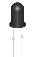
The ID Diode is a semiconductor device that allows current to flow in only one direction, effectively blocking current in the reverse direction. This unidirectional behavior makes it an essential component in various electronic circuits. ID Diodes are commonly used for rectification, signal modulation, voltage regulation, and circuit protection.
Explore Projects Built with ID DIODE
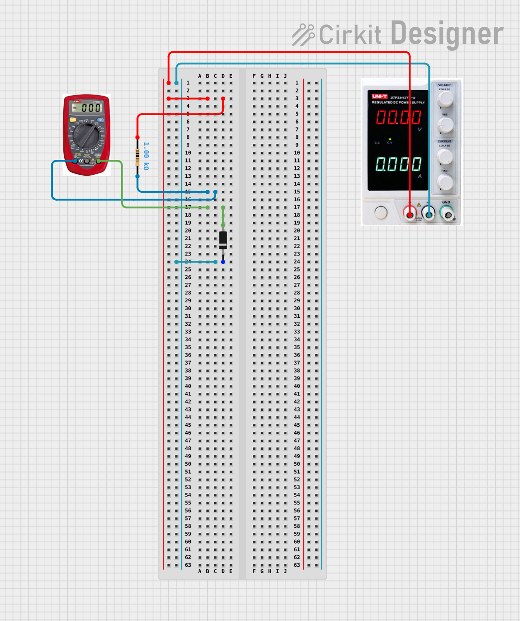

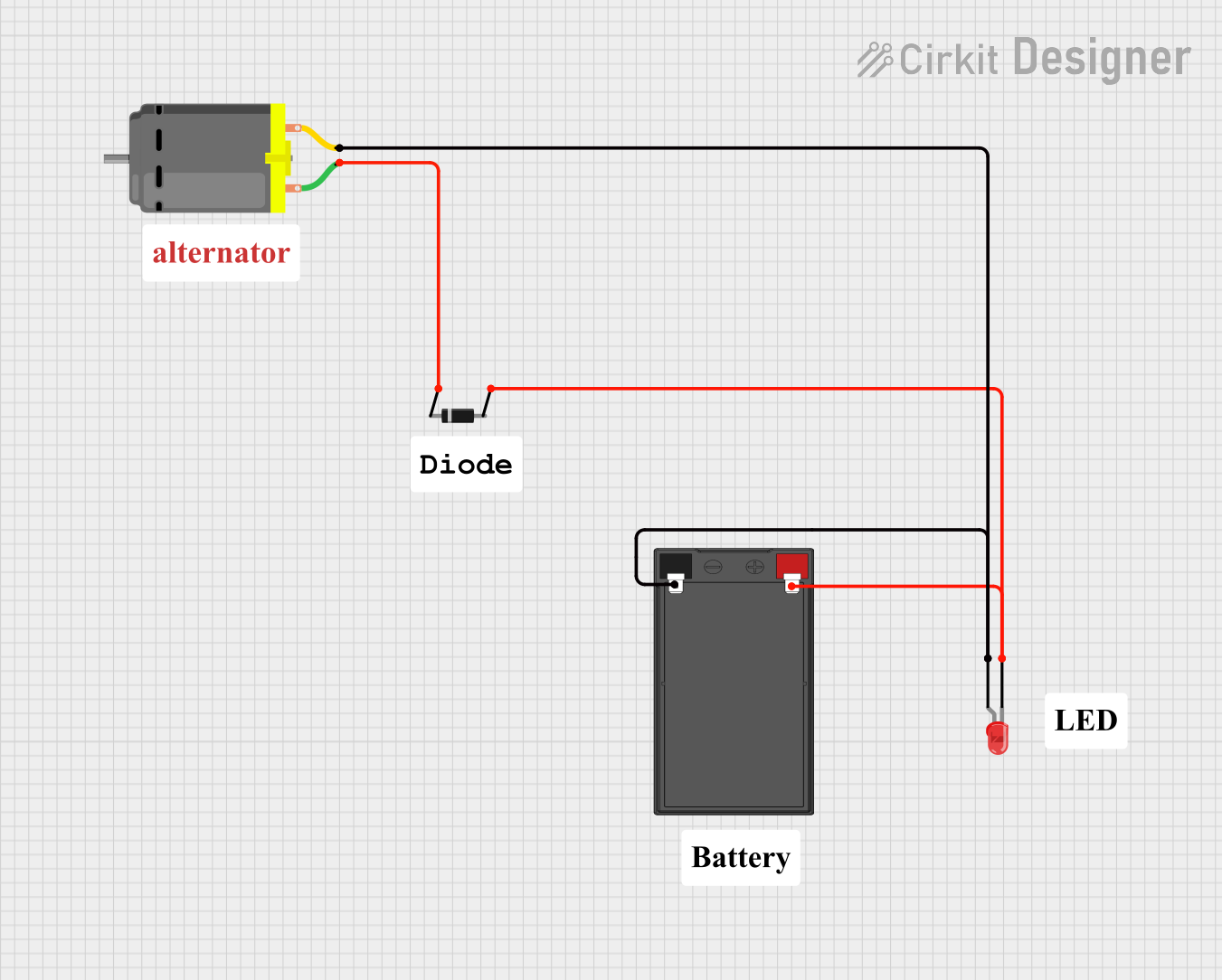
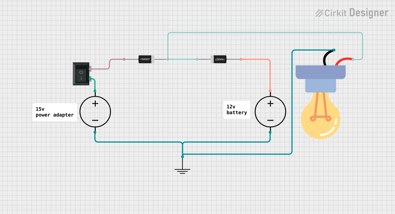
Explore Projects Built with ID DIODE
Common Applications and Use Cases
- Rectification: Converting alternating current (AC) to direct current (DC) in power supplies.
- Signal Modulation: Used in communication systems for signal processing.
- Voltage Clamping: Protecting sensitive components from voltage spikes.
- Reverse Polarity Protection: Preventing damage caused by incorrect power supply connections.
Technical Specifications
Below are the key technical details of a typical ID Diode:
| Parameter | Value |
|---|---|
| Forward Voltage (Vf) | 0.7V (Silicon) / 0.3V (Germanium) |
| Reverse Voltage (Vr) | Up to 1000V (varies by model) |
| Forward Current (If) | 1A to 10A (depending on type) |
| Reverse Current (Ir) | Typically in µA range |
| Power Dissipation | 500mW to 5W |
| Operating Temperature | -55°C to +150°C |
Pin Configuration and Descriptions
The ID Diode has two terminals:
| Pin | Name | Description |
|---|---|---|
| Anode | Positive (+) | Current enters through this terminal when the diode is forward-biased. |
| Cathode | Negative (-) | Current exits through this terminal when the diode is forward-biased. |
The cathode is typically marked with a stripe or band on the diode body for easy identification.
Usage Instructions
How to Use the ID Diode in a Circuit
- Determine the Orientation: Identify the anode and cathode. The cathode is marked with a stripe.
- Connect in Forward Bias: For current to flow, connect the anode to the positive voltage and the cathode to the negative voltage.
- Use a Resistor if Necessary: To limit current, include a resistor in series with the diode if the circuit requires it.
- Check Voltage Ratings: Ensure the diode's reverse voltage rating exceeds the maximum reverse voltage in your circuit.
Example: Using an ID Diode with an Arduino UNO
Below is an example of using an ID Diode for reverse polarity protection in an Arduino UNO circuit:
Circuit Description
- The ID Diode is placed in series with the Arduino's power input to prevent damage from incorrect polarity.
Code Example
/* Example code for Arduino UNO with reverse polarity protection
   using an ID Diode. This code demonstrates a simple LED blink
   program to verify the circuit functionality. */

const int ledPin = 13; // Built-in LED pin on Arduino UNO

void setup() {
  pinMode(ledPin, OUTPUT); // Set LED pin as output
}

void loop() {
  digitalWrite(ledPin, HIGH); // Turn LED on
  delay(1000);                // Wait for 1 second
  digitalWrite(ledPin, LOW);  // Turn LED off
  delay(1000);                // Wait for 1 second
}
Important Considerations and Best Practices
- Heat Dissipation: Ensure adequate cooling if the diode operates near its maximum current rating.
- Voltage Spikes: Use a capacitor in parallel with the diode to suppress voltage spikes in high-speed circuits.
- Reverse Voltage: Avoid exceeding the diode's reverse voltage rating to prevent breakdown.
Troubleshooting and FAQs
Common Issues and Solutions
Diode Not Conducting in Forward Bias:
- Cause: Incorrect orientation of the diode.
- Solution: Verify the anode and cathode connections.
Excessive Heat Generation:
- Cause: Current exceeds the diode's maximum forward current rating.
- Solution: Use a diode with a higher current rating or add a heat sink.
Diode Fails in Reverse Bias:
- Cause: Reverse voltage exceeds the diode's rating.
- Solution: Replace the diode with one that has a higher reverse voltage rating.
FAQs
Q: Can I use an ID Diode for AC signals?
A: Yes, but only for rectification purposes. The diode will block one half of the AC waveform.Q: How do I identify the cathode on a diode?
A: The cathode is marked with a stripe or band on the diode body.Q: What happens if I connect the diode in reverse?
A: The diode will block current flow, protecting the circuit if used for reverse polarity protection.
This concludes the documentation for the ID Diode.