How to Use RM-3100: Examples, Pinouts, and Specs
Introduction
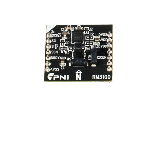
The RM-3100 is a precision resistance meter designed by PNI, capable of measuring a wide range of resistances with high accuracy. This instrument is commonly used in electronic laboratories, manufacturing, and field service applications to assess and troubleshoot resistive components and circuits. Its applications include but are not limited to quality control, component sorting, and material characterization.
Explore Projects Built with RM-3100

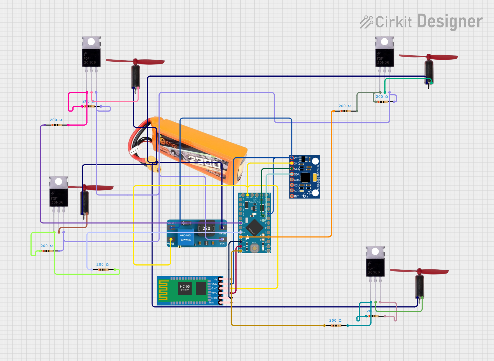


Explore Projects Built with RM-3100
Technical Specifications
Key Technical Details
- Resistance Measurement Range: 0.1 mΩ to 100 MΩ
- Accuracy: ±0.1% of reading ±2 digits
- Measurement Current: Up to 100 mA (depending on range)
- Measurement Voltage: Up to 20 V (compliance voltage)
- Operating Temperature: 0°C to 50°C
- Display: Digital, with backlight
Pin Configuration and Descriptions
| Pin Number | Description | Notes |
|---|---|---|
| 1 | HI terminal | Connect to the positive side of the component under test |
| 2 | LO terminal | Connect to the negative side of the component under test |
| 3 | Guard terminal (optional) | Use to reduce the effect of surface leakage currents |
| 4 | External Trigger (optional) | For synchronization with other equipment |
| 5 | Shield (optional) | Connect to the system ground for noise reduction |
Usage Instructions
How to Use the RM-3100 in a Circuit
Initial Setup:
- Ensure the RM-3100 is turned off before connecting it to a circuit.
- Connect the HI and LO terminals to the component or circuit whose resistance you wish to measure.
Measurement:
- Power on the RM-3100.
- Select the appropriate measurement range manually or set the device to auto-ranging mode.
- If available, use the Guard terminal to improve accuracy in high-impedance measurements.
- Read the resistance value from the digital display.
Best Practices:
- For low-resistance measurements, use four-wire (Kelvin) connections to eliminate lead resistance errors.
- Ensure that the component under test is de-energized to prevent damage to the RM-3100.
- Use the Shield terminal in environments with high electrical noise to maintain measurement integrity.
Troubleshooting and FAQs
Common Issues and Solutions
Inaccurate Readings:
- Check connections to ensure they are secure and using the correct terminals.
- Verify that the component under test is not connected to any power source.
- Use the Guard terminal for high-impedance measurements to reduce the influence of leakage currents.
No Display:
- Ensure the RM-3100 is properly powered and the display brightness is adjusted appropriately.
- Check the power supply and cables for any signs of damage or loose connections.
FAQs
Q: Can the RM-3100 measure inductive or capacitive components?
- A: The RM-3100 is designed for resistance measurements. Inductive or capacitive components should be measured with an LCR meter.
Q: What is the purpose of the Guard terminal?
- A: The Guard terminal is used to reduce the effect of surface leakage currents that can affect high-impedance measurements.
Q: How can I synchronize the RM-3100 with other test equipment?
- A: Use the External Trigger terminal to synchronize the RM-3100 with other instruments for coordinated measurements.
Example Code for Arduino UNO Connection
// This example assumes the use of an external ADC to read the RM-3100 output voltage
// and convert it to a resistance value. The RM-3100 does not directly interface with
// an Arduino UNO but can be used in conjunction with additional components.

#include <Wire.h>
#include <Adafruit_ADS1015.h>

Adafruit_ADS1115 ads;  // Use the ADS1115 for higher resolution

void setup() {
  Serial.begin(9600);
  ads.begin();  // Initialize the ADS1115
}

void loop() {
  int16_t adcReading;  // Stores the ADC reading
  float resistance;    // Calculated resistance value

  adcReading = ads.readADC_SingleEnded(0);  // Read from channel 0
  resistance = convertToResistance(adcReading);  // Convert ADC reading to resistance

  Serial.print("Resistance: ");
  Serial.print(resistance);
  Serial.println(" ohms");

  delay(1000);  // Wait for 1 second before the next reading
}

float convertToResistance(int16_t adcValue) {
  // This function converts the ADC value to resistance using the known parameters
  // of the RM-3100 and the voltage reference of the ADC. The specifics of this
  // conversion will depend on the setup and the external ADC used.
  float voltage = (adcValue * 0.1875)/1000;  // Convert ADC value to voltage (for ADS1115 with gain = 1)
  // The following conversion will depend on the measurement setup
  float resistance = voltage / currentThroughResistor;  // Ohm's Law: R = V/I
  return resistance;
}
Please note that the above code is a hypothetical example of how one might interface the RM-3100 with an Arduino UNO using an external ADC. The actual implementation will vary based on the specific measurement setup and external components used.