How to Use Nano: Examples, Pinouts, and Specs
Introduction
The Arduino Nano ESP32 is a compact, versatile microcontroller designed for embedded systems, robotics, IoT applications, and more. It combines the small form factor of the Nano series with the powerful ESP32 processor, offering advanced wireless connectivity (Wi-Fi and Bluetooth) and robust processing capabilities. Its small size and rich feature set make it ideal for projects requiring portability and high performance.
Explore Projects Built with Nano
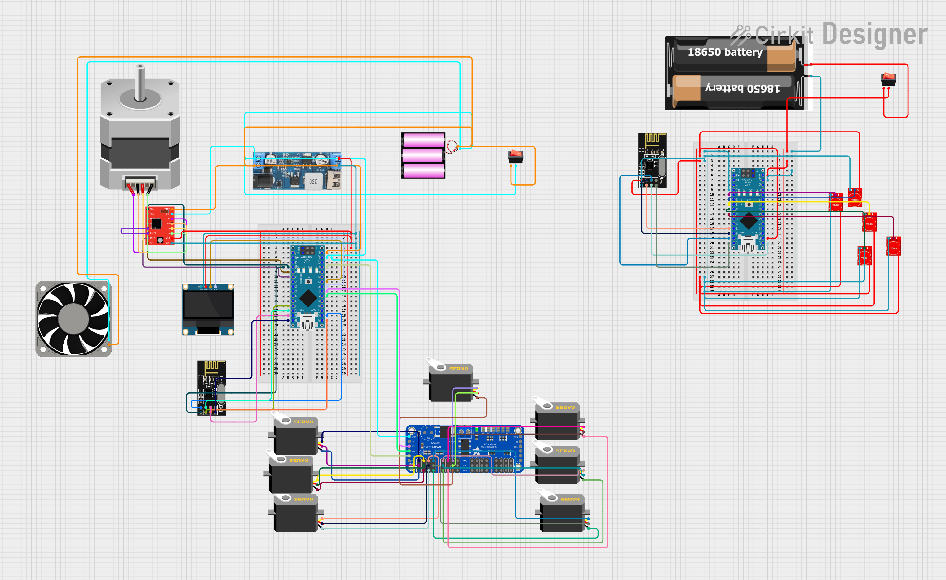
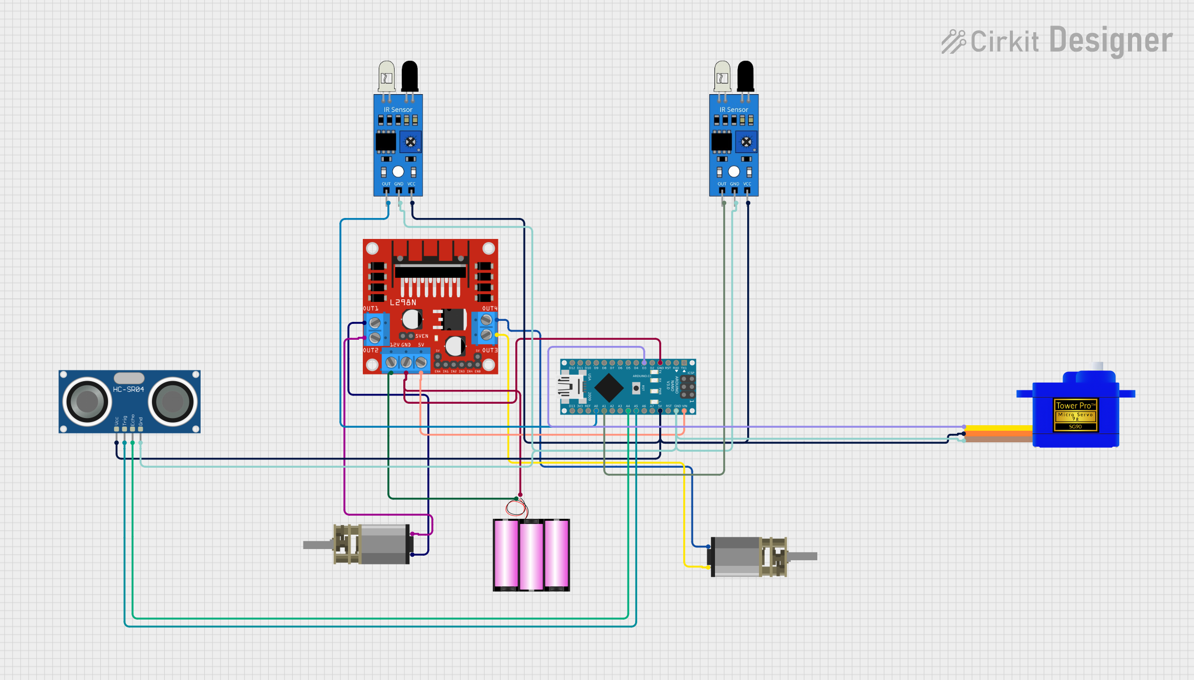
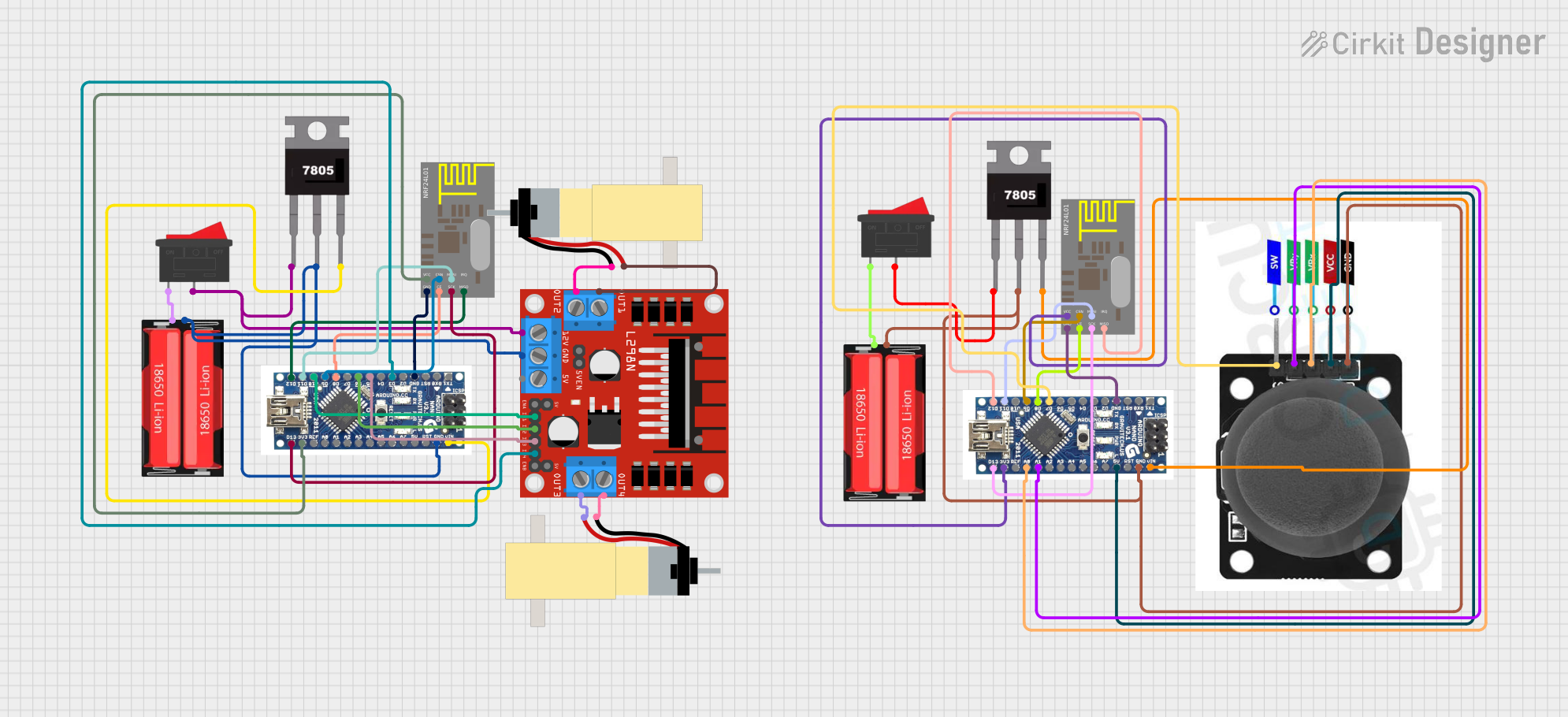
Explore Projects Built with Nano
Common Applications and Use Cases
- IoT devices and smart home automation
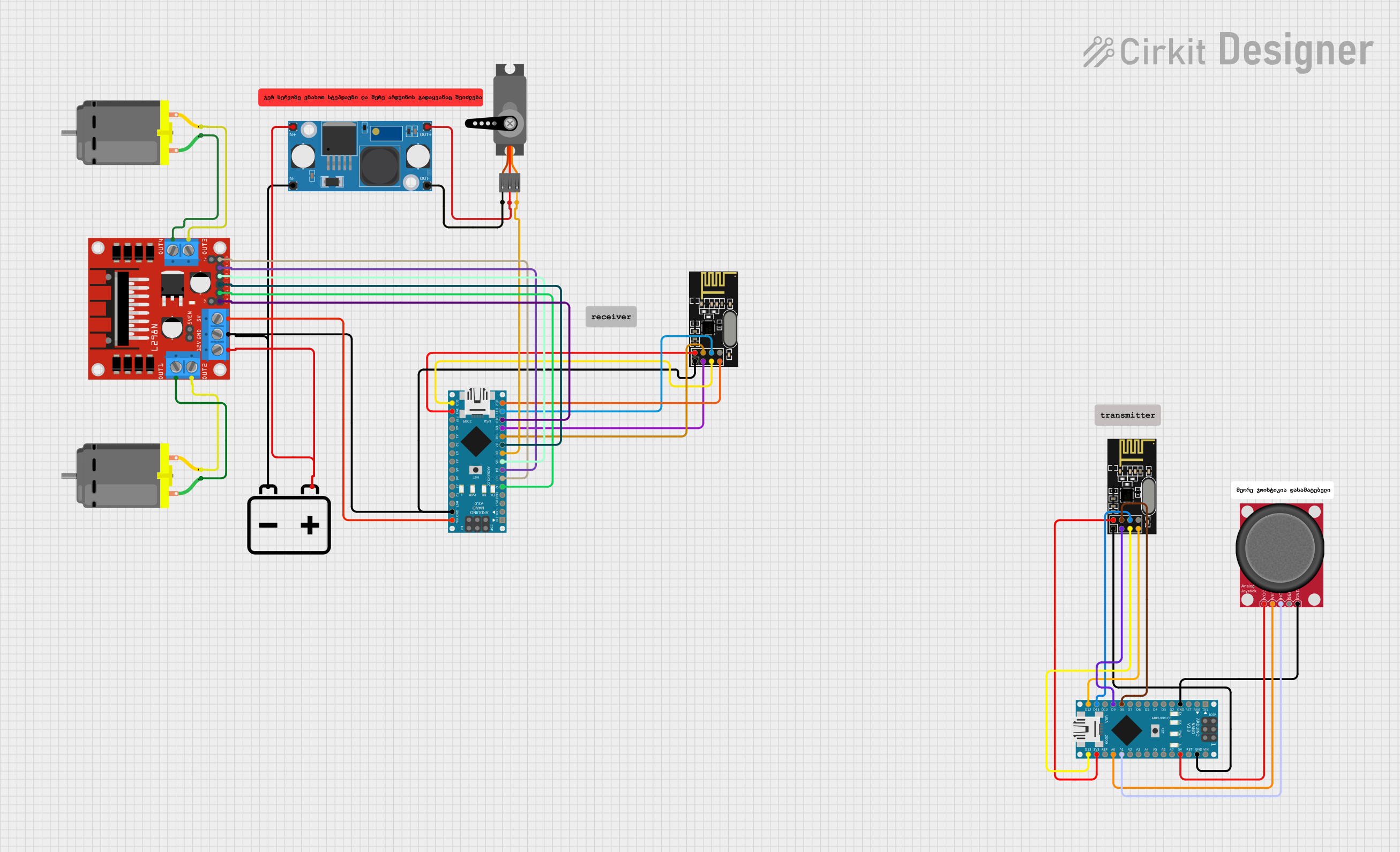
- Robotics and motor control
- Environmental monitoring systems
- Wearable technology
- Data logging and sensor interfacing
- Wireless communication and networking
Technical Specifications
The Arduino Nano ESP32 is built to deliver high performance in a compact package. Below are its key technical details:
Key Technical Details
- Microcontroller: ESP32
- Operating Voltage: 3.3V
- Input Voltage (VIN): 5V (via USB or external power supply)
- Digital I/O Pins: 14 (including PWM support)
- Analog Input Pins: 8
- Flash Memory: 4MB
- SRAM: 520KB
- Clock Speed: 240 MHz
- Wireless Connectivity: Wi-Fi (802.11 b/g/n) and Bluetooth 4.2
- USB Interface: USB-C
- Dimensions: 45mm x 18mm
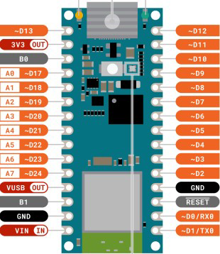
Pin Configuration and Descriptions
The Arduino Nano ESP32 features a standard pinout for easy integration into projects. Below is the pin configuration:
| Pin | Name | Description |
|---|---|---|
| 1 | VIN | Input voltage (5V) for powering the board. |
| 2 | GND | Ground pin. |
| 3 | 3.3V | Regulated 3.3V output. |
| 4-11 | D0-D7 | Digital I/O pins (can be used for PWM, GPIO, or other digital functions). |
| 12-13 | RX, TX | UART communication pins (serial communication). |
| 14-21 | A0-A7 | Analog input pins (10-bit resolution). |
| 22 | RST | Reset pin to restart the microcontroller. |
| 23 | SDA | I2C data line. |
| 24 | SCL | I2C clock line. |
| 25 | EN | Enable pin to activate or deactivate the board. |
Usage Instructions
The Arduino Nano ESP32 is easy to use and program, making it suitable for both beginners and advanced users. Below are the steps and best practices for using the component:
How to Use the Component in a Circuit
Powering the Board:
- Connect the board to a USB-C cable for power and programming.
- Alternatively, supply 5V to the VIN pin and connect GND to the ground of your power source.
Programming the Board:
- Install the Arduino IDE and add the ESP32 board support package.
- Select "Arduino Nano ESP32" as the board in the Tools menu.
- Write your code and upload it via the USB-C connection.
Connecting Peripherals:
- Use the digital pins (D0-D7) for controlling LEDs, motors, or other digital devices.
- Use the analog pins (A0-A7) for reading sensor data.
- For I2C devices, connect SDA and SCL to the corresponding pins on the peripheral.
Important Considerations and Best Practices
- Ensure the input voltage does not exceed 5V to avoid damaging the board.
- Use level shifters when interfacing with 5V logic devices, as the Nano ESP32 operates at 3.3V.
- Avoid drawing excessive current from the 3.3V pin, as it is limited by the onboard regulator.
- Use proper decoupling capacitors when connecting external components to reduce noise.
Example Code for Arduino Nano ESP32
Below is an example of how to use the Nano ESP32 to read a temperature sensor and send the data over Wi-Fi:
#include <WiFi.h> // Include the Wi-Fi library

// Wi-Fi credentials
const char* ssid = "Your_SSID";       // Replace with your Wi-Fi network name
const char* password = "Your_Password"; // Replace with your Wi-Fi password

// Analog pin for temperature sensor
const int tempPin = A0;

void setup() {
  Serial.begin(115200); // Initialize serial communication
  WiFi.begin(ssid, password); // Connect to Wi-Fi

  // Wait for Wi-Fi connection
  while (WiFi.status() != WL_CONNECTED) {
    delay(1000);
    Serial.println("Connecting to Wi-Fi...");
  }
  Serial.println("Connected to Wi-Fi!");
}

void loop() {
  int sensorValue = analogRead(tempPin); // Read temperature sensor value
  float voltage = sensorValue * (3.3 / 1023.0); // Convert to voltage
  float temperature = (voltage - 0.5) * 100.0; // Convert to temperature (Celsius)

  // Print temperature to Serial Monitor
  Serial.print("Temperature: ");
  Serial.print(temperature);
  Serial.println(" °C");

  delay(2000); // Wait 2 seconds before next reading
}
Troubleshooting and FAQs
Common Issues Users Might Face
Board Not Detected by the Arduino IDE:
- Ensure the correct board and port are selected in the Tools menu.
- Install the necessary drivers for the USB-C interface.
Wi-Fi Connection Fails:
- Double-check the SSID and password in your code.
- Ensure the Wi-Fi network is active and within range.
Analog Readings Are Inaccurate:
- Verify the sensor connections and ensure proper grounding.
- Use a stable power supply to minimize noise.
Board Overheats:
- Check for short circuits or excessive current draw from peripherals.
- Ensure proper ventilation around the board.
Solutions and Tips for Troubleshooting
- Use the Serial Monitor to debug your code and check for error messages.
- Update the ESP32 board package in the Arduino IDE to the latest version.
- Test the board with a simple "Blink" sketch to verify basic functionality.
- If the board becomes unresponsive, press the reset button or disconnect and reconnect the power.
By following this documentation, you can effectively utilize the Arduino Nano ESP32 in your projects and troubleshoot common issues with ease.