How to Use BUCK: Examples, Pinouts, and Specs
Introduction
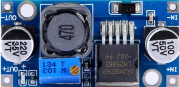
The HUAREW BUCK DC/DC converter is a highly efficient DC-DC step-down voltage regulator designed to convert a higher input voltage to a lower output voltage while increasing current. This component is widely used in power management systems due to its ability to deliver stable and efficient power conversion. It is ideal for applications requiring compact, reliable, and energy-efficient voltage regulation.
Explore Projects Built with BUCK


Explore Projects Built with BUCK
Common Applications and Use Cases
- Power supply for microcontrollers and embedded systems
- Battery-powered devices
- LED drivers
- Industrial automation systems
- Consumer electronics
- Renewable energy systems (e.g., solar power regulators)
Technical Specifications
The following table outlines the key technical specifications of the HUAREW BUCK DC/DC converter:
| Parameter | Value |
|---|---|
| Input Voltage Range | 4.5V to 40V |
| Output Voltage Range | 1.25V to 37V |
| Output Current | Up to 3A |
| Efficiency | Up to 92% |
| Switching Frequency | 150 kHz |
| Operating Temperature | -40°C to +85°C |
| Package Type | TO-220 or SMD (varies by model) |
Pin Configuration and Descriptions
The pinout of the HUAREW BUCK DC/DC converter is as follows:
| Pin Number | Pin Name | Description |
|---|---|---|
| 1 | VIN | Input voltage pin. Connect to the higher voltage source. |
| 2 | GND | Ground pin. Connect to the circuit ground. |
| 3 | VOUT | Output voltage pin. Provides the regulated lower voltage. |
| 4 | FB | Feedback pin. Used to set the output voltage via a resistor divider. |
| 5 | EN (optional) | Enable pin. Used to turn the converter on or off (if available). |
Usage Instructions
How to Use the Component in a Circuit
- Input Voltage Connection: Connect the input voltage source (e.g., a battery or power supply) to the
VINpin. Ensure the input voltage is within the specified range (4.5V to 40V). - Output Voltage Adjustment: Use a resistor divider network connected to the
FBpin to set the desired output voltage. The formula for output voltage is: [ V_{OUT} = V_{REF} \times \left(1 + \frac{R1}{R2}\right) ] where ( V_{REF} ) is typically 1.25V. - Output Connection: Connect the load to the
VOUTpin. Ensure the load does not exceed the maximum output current (3A). - Enable Pin (if available): If the
ENpin is present, connect it to a logic high signal to enable the converter or to ground to disable it. - Inductor and Capacitor Selection: Choose an appropriate inductor and output capacitor based on the desired output voltage and current. Refer to the datasheet for recommended values.
Important Considerations and Best Practices
- Heat Dissipation: Ensure proper heat dissipation by using a heatsink or adequate PCB thermal design, especially for high-current applications.
- Input and Output Capacitors: Use low-ESR capacitors for input and output filtering to minimize voltage ripple.
- PCB Layout: Keep the traces for the input, output, and ground connections as short and wide as possible to reduce resistance and noise.
- Protection: Add a fuse or overcurrent protection circuit to safeguard the converter and connected devices.
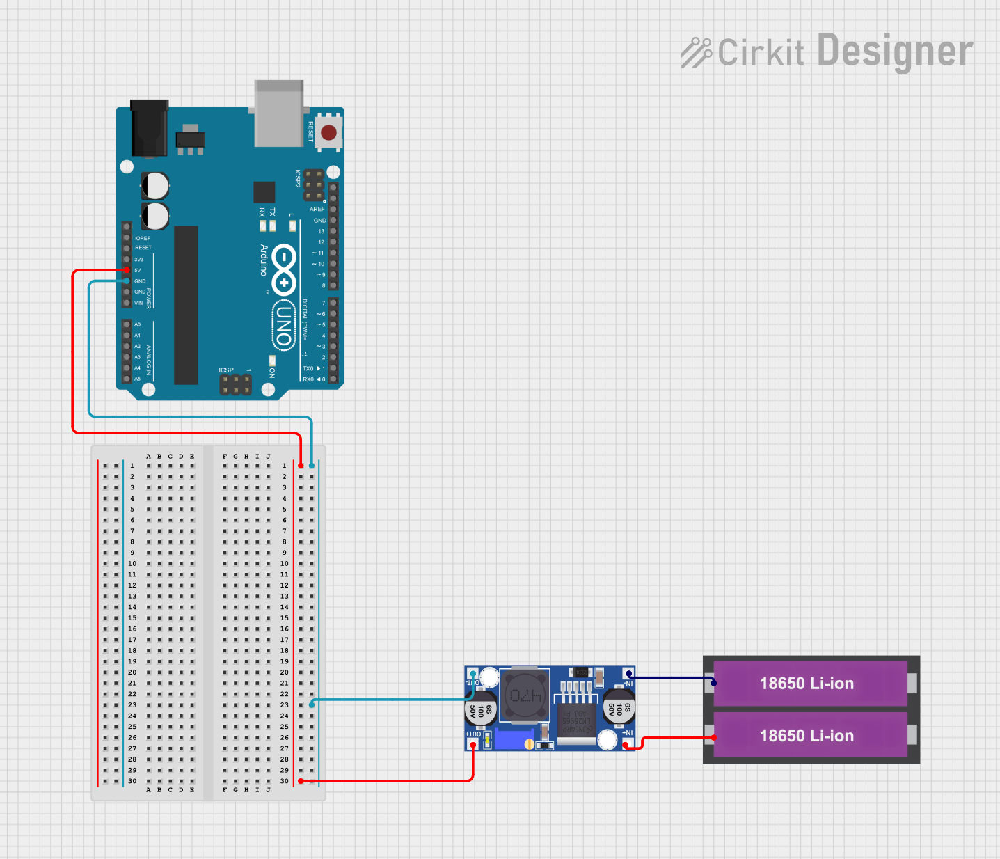
Example: Connecting to an Arduino UNO
The HUAREW BUCK DC/DC converter can be used to power an Arduino UNO by stepping down a 12V input to 5V. Below is an example circuit and Arduino code:
Circuit Setup
- Connect a 12V power supply to the
VINpin of the BUCK converter. - Adjust the output voltage to 5V using the feedback resistor network.
- Connect the
VOUTpin to the 5V pin of the Arduino UNO. - Connect the
GNDpin of the BUCK converter to the Arduino's GND.
Arduino Code Example
// Example code to blink an LED using an Arduino UNO powered by the BUCK DC/DC converter

const int ledPin = 13; // Pin connected to the onboard LED

void setup() {
  pinMode(ledPin, OUTPUT); // Set the LED pin as an output
}

void loop() {
  digitalWrite(ledPin, HIGH); // Turn the LED on
  delay(1000);                // Wait for 1 second
  digitalWrite(ledPin, LOW);  // Turn the LED off
  delay(1000);                // Wait for 1 second
}
Troubleshooting and FAQs
Common Issues and Solutions
No Output Voltage
- Cause: Incorrect input voltage or loose connections.
- Solution: Verify the input voltage is within the specified range and check all connections.
Excessive Heat
- Cause: Overloading the converter or insufficient heat dissipation.
- Solution: Reduce the load current or improve heat dissipation using a heatsink.
High Output Voltage Ripple
- Cause: Inadequate input/output capacitors or poor PCB layout.
- Solution: Use low-ESR capacitors and optimize the PCB layout.
Converter Not Starting
- Cause: Enable pin not connected or set to logic low.
- Solution: Ensure the
ENpin is connected to a logic high signal.
FAQs
Can the BUCK DC/DC converter handle reverse polarity?
- No, reverse polarity can damage the converter. Use a diode for reverse polarity protection.
What is the maximum efficiency of the converter?
- The maximum efficiency is up to 92%, depending on the input and output voltage conditions.
Can I use this converter for AC input?
- No, the BUCK DC/DC converter is designed for DC input only. Use a rectifier circuit to convert AC to DC before using the converter.
How do I calculate the inductor value?
- Refer to the datasheet for recommended inductor values based on the output voltage and current. A general guideline is to choose an inductor with a current rating higher than the maximum load current.
By following this documentation, you can effectively integrate the HUAREW BUCK DC/DC converter into your projects for efficient and reliable power management.