How to Use KY-051Voltage Translator / Level Shifter: Examples, Pinouts, and Specs
Introduction
The KY-051 Voltage Translator, manufactured by Joy-It, is a versatile device designed to convert voltage levels between different systems. It enables seamless communication between components operating at varying voltage levels, such as 3.3V and 5V logic devices. This makes it an essential tool for interfacing modern microcontrollers, sensors, and other peripherals that may not share the same voltage standards.
Explore Projects Built with KY-051Voltage Translator / Level Shifter


Explore Projects Built with KY-051Voltage Translator / Level Shifter
Common Applications and Use Cases
- Interfacing 3.3V microcontrollers (e.g., ESP32, Raspberry Pi) with 5V peripherals (e.g., Arduino, sensors).
- Bidirectional communication between devices with different voltage levels.
- Voltage level shifting for I2C, UART, SPI, and other communication protocols.
- Protecting low-voltage devices from damage caused by higher voltage signals.
Technical Specifications
The KY-051 Voltage Translator is a bidirectional level shifter that supports up to four independent channels. Below are its key technical details:
Key Technical Details
- Operating Voltage (Low Side): 1.8V to 3.6V
- Operating Voltage (High Side): 3.6V to 6V
- Maximum Current per Channel: 50mA
- Number of Channels: 4 (bidirectional)
- Communication Protocols Supported: I2C, UART, SPI, GPIO
- Dimensions: 15mm x 15mm
- Manufacturer Part ID: KY-051
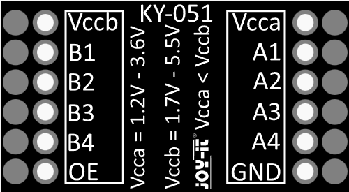
Pin Configuration and Descriptions
The KY-051 module has 8 pins, divided into two groups for the low-voltage (LV) and high-voltage (HV) sides. Below is the pinout:
| Pin | Name | Description |
|---|---|---|
| 1 | LV | Low-voltage power supply input (1.8V to 3.6V). |
| 2 | GND | Ground connection (shared between LV and HV sides). |
| 3 | LV1 | Low-voltage side signal for channel 1. |
| 4 | LV2 | Low-voltage side signal for channel 2. |
| 5 | HV | High-voltage power supply input (3.6V to 6V). |
| 6 | HV1 | High-voltage side signal for channel 1. |
| 7 | HV2 | High-voltage side signal for channel 2. |
| 8 | GND | Ground connection (redundant, for convenience). |
For channels 3 and 4, the pin configuration follows the same pattern (LV3 ↔ HV3, LV4 ↔ HV4).
Usage Instructions
How to Use the KY-051 in a Circuit
Power Connections:
- Connect the low-voltage power supply (e.g., 3.3V) to the
LVpin. - Connect the high-voltage power supply (e.g., 5V) to the
HVpin. - Ensure both power supplies share a common ground by connecting
GNDto the ground of your circuit.
- Connect the low-voltage power supply (e.g., 3.3V) to the
Signal Connections:
- Connect the low-voltage signal lines to the
LVxpins. - Connect the corresponding high-voltage signal lines to the
HVxpins. - The KY-051 automatically handles bidirectional communication, so no additional configuration is needed.
- Connect the low-voltage signal lines to the
Verify Connections:
- Double-check all connections to ensure proper voltage levels are applied to the
LVandHVpins. - Ensure the ground connections are secure to avoid communication issues.
- Double-check all connections to ensure proper voltage levels are applied to the
Important Considerations and Best Practices
- Voltage Compatibility: Ensure the voltage levels on the
LVandHVsides are within the specified ranges to prevent damage to the module. - Current Limitations: Do not exceed the maximum current rating of 50mA per channel.
- Signal Integrity: Use short, high-quality wires to minimize noise and signal degradation, especially for high-speed communication protocols like SPI.
- Pull-Up Resistors for I2C: If using the KY-051 for I2C communication, ensure appropriate pull-up resistors are present on both the
LVandHVsides.
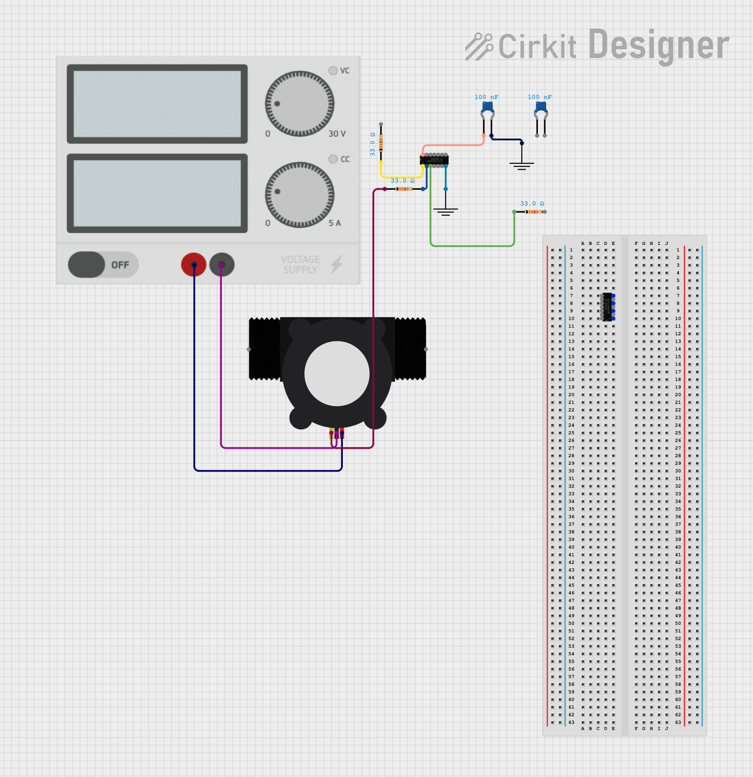
Example: Connecting KY-051 to an Arduino UNO
Below is an example of using the KY-051 to interface a 3.3V sensor with a 5V Arduino UNO:
Circuit Diagram
- Connect the Arduino's 5V pin to the
HVpin of the KY-051. - Connect the sensor's 3.3V power pin to the
LVpin of the KY-051. - Connect the sensor's data line to
LV1and the corresponding Arduino pin toHV1. - Connect all grounds (
GND) together.
Arduino Code Example
// Example: Reading data from a 3.3V sensor using KY-051 with Arduino UNO

#include <Wire.h> // Include Wire library for I2C communication

#define SENSOR_ADDRESS 0x40 // Replace with your sensor's I2C address

void setup() {
  Wire.begin(); // Initialize I2C communication
  Serial.begin(9600); // Start serial communication for debugging
  Serial.println("KY-051 Level Shifter Example");
}

void loop() {
  Wire.beginTransmission(SENSOR_ADDRESS); // Start communication with sensor
  Wire.write(0x00); // Replace with the sensor's register address
  Wire.endTransmission();

  Wire.requestFrom(SENSOR_ADDRESS, 2); // Request 2 bytes of data
  if (Wire.available() == 2) {
    int data = Wire.read() << 8 | Wire.read(); // Combine two bytes into one value
    Serial.print("Sensor Data: ");
    Serial.println(data); // Print the sensor data
  } else {
    Serial.println("Error: No data received from sensor");
  }

  delay(1000); // Wait 1 second before the next reading
}
Troubleshooting and FAQs
Common Issues and Solutions
No Communication Between Devices:
- Cause: Incorrect voltage levels or missing ground connection.
- Solution: Verify that the
LVandHVpins are connected to the correct voltage sources and that all grounds are connected.
Signal Distortion or Noise:
- Cause: Long wires or poor-quality connections.
- Solution: Use shorter wires and ensure secure connections. Add decoupling capacitors if necessary.
I2C Communication Fails:
- Cause: Missing or incorrect pull-up resistors.
- Solution: Add appropriate pull-up resistors (e.g., 4.7kΩ) to the SDA and SCL lines on both the
LVandHVsides.
Overheating of the KY-051:
- Cause: Exceeding the maximum current rating.
- Solution: Ensure the current through each channel does not exceed 50mA.
FAQs
Q: Can the KY-051 be used for analog signals?
A: No, the KY-051 is designed for digital signals only. It is not suitable for analog voltage level shifting.Q: Does the KY-051 require external power?
A: Yes, theLVandHVpins must be connected to external power supplies corresponding to the voltage levels of the devices being interfaced.Q: Can I use the KY-051 for SPI communication?
A: Yes, the KY-051 supports SPI communication. Ensure proper connections for the MOSI, MISO, SCK, and CS lines.Q: Is the KY-051 compatible with 1.8V devices?
A: Yes, theLVside supports voltages as low as 1.8V, making it compatible with 1.8V devices.