How to Use trafo : Examples, Pinouts, and Specs
Introduction
A transformer, commonly referred to as a "trafo," is an electrical device designed to transfer electrical energy between two or more circuits via electromagnetic induction. It is primarily used to step up (increase) or step down (decrease) voltage levels in electrical systems. Transformers are essential in power distribution, ensuring efficient energy transfer over long distances and adapting voltage levels for various applications.
Explore Projects Built with trafo


Explore Projects Built with trafo
Common Applications and Use Cases
- Power distribution in electrical grids
- Voltage regulation in electronic devices
- Isolation between circuits for safety
- Impedance matching in audio systems
- Use in power supplies for converting AC voltage levels
Technical Specifications
Below are the general technical specifications for the Arduino-manufactured transformer (part ID: trafo). These specifications may vary depending on the specific model or application.
Key Technical Details
- Input Voltage (Primary): 110V AC or 220V AC (depending on model)
- Output Voltage (Secondary): 5V, 12V, 24V AC (model-dependent)
- Frequency: 50Hz or 60Hz
- Power Rating: 10W to 100W (varies by model)
- Efficiency: Typically 90% or higher
- Insulation Resistance: >100MΩ at 500V DC
- Operating Temperature Range: -20°C to +70°C
- Core Material: Silicon steel or ferrite (depending on application)
Pin Configuration and Descriptions
The transformer typically has two sets of terminals: primary and secondary. Below is a table describing the pin configuration.
| Pin Name | Description |
|---|---|
| Primary Input (+) | Connects to the live AC input voltage (e.g., 110V or 220V AC). |
| Primary Input (-) | Connects to the neutral AC input voltage. |
| Secondary Output (+) | Provides the stepped-up or stepped-down AC voltage output. |
| Secondary Output (-) | Ground or neutral for the secondary output voltage. |
Note: Some transformers may include additional taps for multiple voltage outputs or center-tapped configurations.
Usage Instructions
How to Use the Transformer in a Circuit
Determine Voltage Requirements:
- Identify the input voltage (primary) and the desired output voltage (secondary) for your application.
- Ensure the transformer’s power rating matches or exceeds the load requirements.
Connect the Primary Side:
- Connect the primary input terminals to the AC mains supply (e.g., 110V or 220V AC).
- Use proper insulation and safety precautions when handling high-voltage connections.
Connect the Secondary Side:
- Connect the secondary output terminals to the load or circuit requiring the stepped-up or stepped-down voltage.
- If the transformer has multiple secondary outputs, ensure you use the correct terminals for your desired voltage.
Test the Circuit:
- Power on the transformer and measure the output voltage using a multimeter to confirm it matches the expected value.
- Verify that the load operates correctly without exceeding the transformer’s power rating.
Important Considerations and Best Practices
- Safety First: Always disconnect the transformer from the power source before making any connections or modifications.
- Overloading: Avoid exceeding the transformer’s power rating, as this can cause overheating and damage.
- Grounding: Properly ground the transformer to prevent electrical hazards.
- Isolation: Use transformers with isolation features for added safety in sensitive applications.
- Heat Dissipation: Ensure adequate ventilation or cooling to prevent overheating during prolonged use.
Example: Using a Transformer with an Arduino UNO
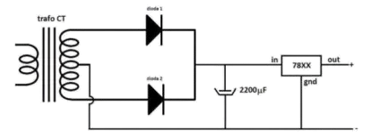
Transformers are often used to power Arduino projects by stepping down AC voltage to a suitable DC voltage. Below is an example of how to use a transformer with a rectifier circuit to power an Arduino UNO.
Circuit Diagram
- Connect the transformer’s secondary output to a bridge rectifier.
- Add a smoothing capacitor (e.g., 1000µF) to the rectifier output.
- Use a voltage regulator (e.g., 7805) to provide a stable 5V DC output for the Arduino UNO.
Sample Code
// Example code for Arduino UNO powered by a transformer-based power supply
// This code blinks an LED connected to pin 13

void setup() {
  pinMode(13, OUTPUT); // Set pin 13 as an output for the LED
}

void loop() {
  digitalWrite(13, HIGH); // Turn the LED on
  delay(1000);            // Wait for 1 second
  digitalWrite(13, LOW);  // Turn the LED off
  delay(1000);            // Wait for 1 second
}
Note: Ensure the transformer and rectifier circuit provide a stable 5V DC output before connecting to the Arduino UNO.
Troubleshooting and FAQs
Common Issues and Solutions
No Output Voltage:
- Cause: Incorrect wiring or a blown fuse.
- Solution: Double-check all connections and replace the fuse if necessary.
Overheating Transformer:
- Cause: Overloading or insufficient ventilation.
- Solution: Reduce the load or improve airflow around the transformer.
Voltage Drop Under Load:
- Cause: Transformer power rating is too low for the load.
- Solution: Use a transformer with a higher power rating.
Humming Noise:
- Cause: Loose core laminations or excessive load.
- Solution: Tighten the core or reduce the load.
FAQs
Q: Can I use a transformer to convert DC voltage?
A: No, transformers only work with AC voltage. To convert DC, use a DC-DC converter.Q: How do I calculate the required transformer power rating?
A: Multiply the load current by the output voltage and add a safety margin (e.g., 20%).Q: Can I use a transformer outdoors?
A: Only if it is specifically designed for outdoor use and properly enclosed to protect against moisture and dust.Q: What is the difference between a step-up and step-down transformer?
A: A step-up transformer increases voltage, while a step-down transformer decreases voltage.
By following this documentation, users can safely and effectively integrate the Arduino-manufactured transformer (trafo) into their projects.