How to Use Raspberry Pi Zero: Examples, Pinouts, and Specs
Introduction
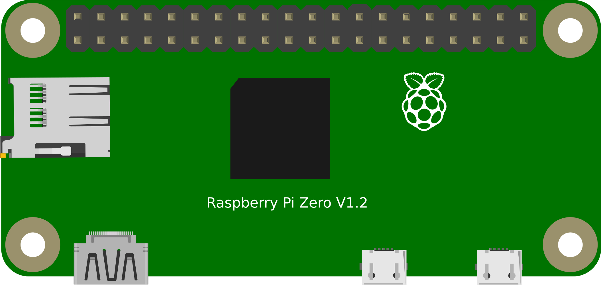
The Raspberry Pi Zero is a low-cost, ultra-small form factor single-board computer developed by the Raspberry Pi Foundation. It is designed to be affordable and accessible for hobbyists, educators, and professionals looking to create compact embedded systems. The Raspberry Pi Zero is commonly used in applications such as DIY electronics projects, IoT devices, and as a learning tool for programming and computer science education.
Explore Projects Built with Raspberry Pi Zero
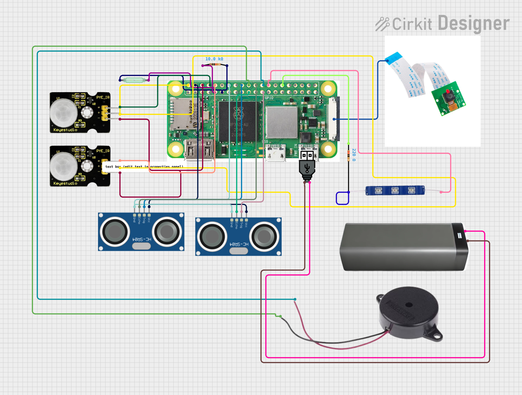

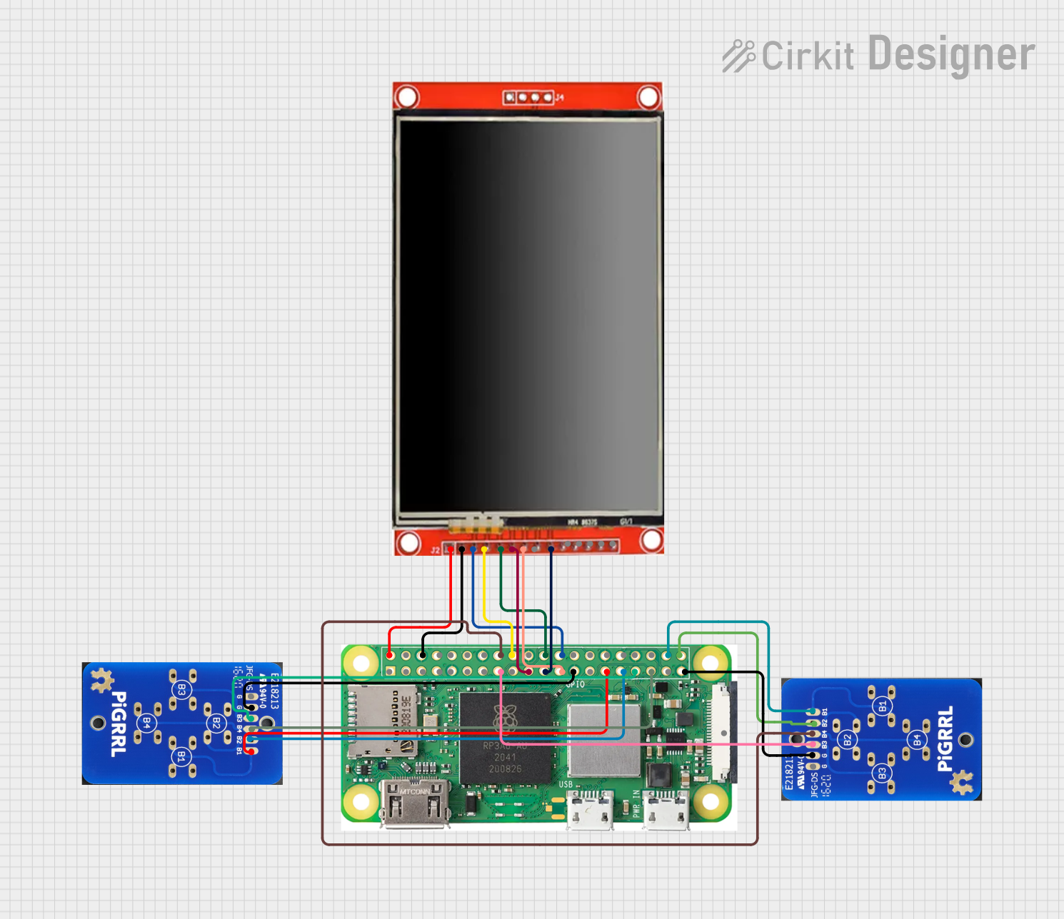
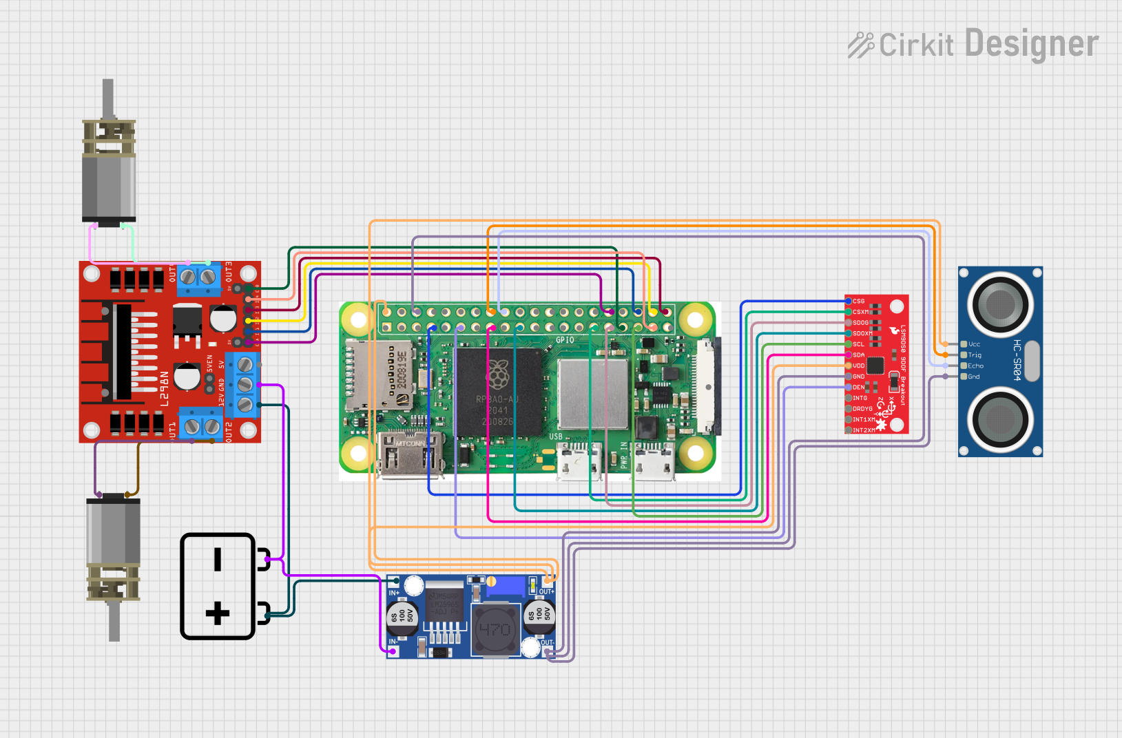
Explore Projects Built with Raspberry Pi Zero
Technical Specifications
General Specifications
- Processor: Single-core ARM11 running at 1GHz
- RAM: 512MB LPDDR2 SDRAM
- Storage: microSD card slot for operating system and data
- Video & Audio Output: Mini-HDMI and unpopulated composite video header
- Power Input: 5V, supplied via micro USB connector
- Dimensions: 65mm x 30mm x 5mm
Connectivity
- USB: 1 x Micro-USB for data
- USB: 1 x Micro-USB for power
- GPIO: 40-pin GPIO header, unpopulated
- Camera Interface (CSI): Unpopulated 15-pin MIPI Camera Serial Interface
Pin Configuration
| Pin Number | Description | Pin Number | Description |
|---|---|---|---|
| 1 | 3V3 Power | 2 | 5V Power |
| 3 | GPIO2 (SDA1, I2C) | 4 | 5V Power |
| 5 | GPIO3 (SCL1, I2C) | 6 | Ground |
| ... | ... | ... | ... |
| 39 | Ground | 40 | GPIO21 (SPI0_MOSI) |
Note: The above table is a partial representation of the GPIO header. For the full pinout, refer to the official Raspberry Pi Zero documentation.
Usage Instructions
Setting Up the Raspberry Pi Zero
Prepare the microSD Card:
- Download the latest version of Raspberry Pi OS from the official Raspberry Pi website.
- Use imaging software to write the OS image to the microSD card.
Connect Peripherals:
- Insert the microSD card into the slot on the Raspberry Pi Zero.
- Connect a mini-HDMI cable to a display.
- Connect a USB keyboard and mouse via a USB OTG cable.
- If necessary, connect a USB hub to expand the number of USB ports.
Power Up:
- Connect the micro USB power cable to the Raspberry Pi Zero and to a 5V power source.
Important Considerations and Best Practices
- Power Supply: Ensure that the power supply is capable of providing at least 1.2A for the Raspberry Pi Zero to function reliably.
- Heat Management: The Raspberry Pi Zero can get warm under load. Consider using heat sinks or ensuring proper ventilation in your project enclosure.
- GPIO Usage: When interfacing with the GPIO pins, be cautious to avoid short circuits or applying incorrect voltages that could damage the board.
- Static Discharge: Handle the Raspberry Pi Zero with care to prevent static discharge from damaging the board.
Troubleshooting and FAQs
Common Issues
- Pi Zero Not Booting: Ensure the microSD card is properly inserted and contains a valid OS image. Check that the power supply is adequate.
- Video Output Issues: Verify that the mini-HDMI cable is securely connected and that the display is compatible and set to the correct input.
- USB Device Not Recognized: Check the connection of the USB OTG cable and ensure that the USB device is compatible with the Raspberry Pi Zero.
FAQs
Q: Can I use a standard HDMI cable with the Raspberry Pi Zero? A: No, the Raspberry Pi Zero requires a mini-HDMI to standard HDMI cable or an adapter.
Q: Does the Raspberry Pi Zero have Wi-Fi? A: The standard Raspberry Pi Zero does not have built-in Wi-Fi. However, the Raspberry Pi Zero W variant includes Wi-Fi and Bluetooth connectivity.
Q: How do I connect to the internet without Wi-Fi? A: You can use a USB Ethernet adapter or a USB Wi-Fi dongle with the Raspberry Pi Zero.
Q: Can I use any microSD card with the Raspberry Pi Zero? A: It is recommended to use a high-quality, class 10 microSD card for better performance and reliability.
Example Code for Raspberry Pi Zero with Arduino UNO
The Raspberry Pi Zero can be used in conjunction with an Arduino UNO for various projects. Below is an example of how to establish serial communication between the two devices.
Raspberry Pi Zero Python Code to Send Data to Arduino UNO
import serial import time
Establish a serial connection (ensure the port and baud rate match the Arduino configuration)
ser = serial.Serial('/dev/ttyAMA0', 9600, timeout=1) ser.flush()
while True: ser.write(b"Hello Arduino\n") # Send a message to the Arduino time.sleep(1) # Wait for a second
```cpp
// Arduino UNO Code to Receive Data from Raspberry Pi Zero
#include <SoftwareSerial.h>

SoftwareSerial piSerial(10, 11); // RX, TX

void setup() {
  pinMode(LED_BUILTIN, OUTPUT);
  piSerial.begin(9600); // Start the software serial communication
}

void loop() {
  if (piSerial.available() > 0) {
    String data = piSerial.readStringUntil('\n'); // Read the incoming data
    if (data == "Hello Arduino") {
      digitalWrite(LED_BUILTIN, HIGH); // Turn on the built-in LED
      delay(500);                      // Keep it on for 500ms
      digitalWrite(LED_BUILTIN, LOW);  // Turn off the LED
    }
  }
}
Note: The above code snippets are for demonstration purposes. Ensure that the Raspberry Pi Zero and Arduino UNO are correctly connected via serial communication and that the appropriate serial ports are used in the code.