
How to Use SO20W: Examples, Pinouts, and Specs
 Design with SO20W in Cirkit Designer
Introduction
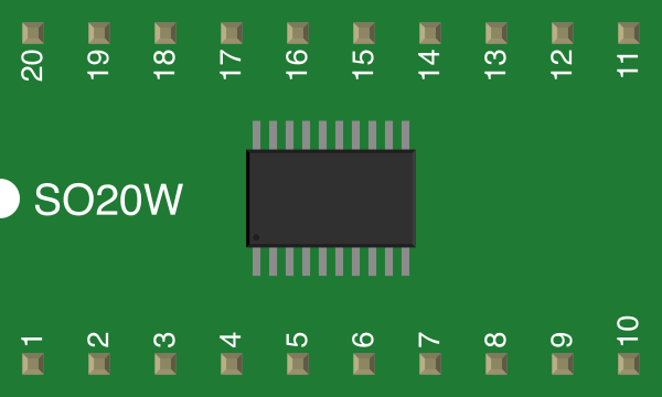
The SO20W is a surface-mount package with 20 pins, designed for integrated circuits. Its compact size and wide pin spacing make it ideal for applications where space is limited but reliable electrical connections are required. The SO20W package is commonly used in microcontrollers, memory chips, and other ICs in consumer electronics, automotive systems, and industrial devices.
Explore Projects Built with SO20W
 Open Project in Cirkit Designer
 Open Project in Cirkit Designer
 Open Project in Cirkit Designer
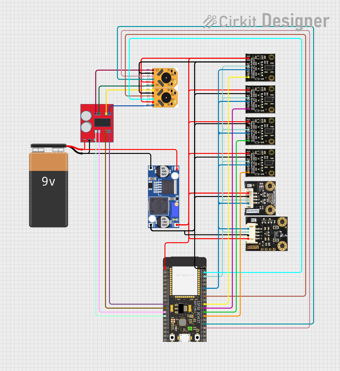 Open Project in Cirkit Designer
Explore Projects Built with SO20W
Open Project in Cirkit DesignerOpen Project in Cirkit DesignerOpen Project in Cirkit DesignerOpen Project in Cirkit DesignerCommon Applications and Use Cases
- Microcontrollers and digital signal processors (DSPs)
- Memory ICs (e.g., EEPROM, Flash)
- Power management ICs
- Communication modules
- Compact electronic devices requiring high pin density
Technical Specifications
Key Technical Details
- Package Type: SO20W (Small Outline, 20 pins, Wide body)
- Pin Count: 20
- Body Width: 7.5 mm (wide body)
- Pitch: 1.27 mm (distance between adjacent pins)
- Mounting Type: Surface Mount Technology (SMT)
- Thermal Resistance: Varies by IC, typically 50–100 °C/W
- Operating Temperature Range: -40 °C to +125 °C (dependent on IC specifications)
- Moisture Sensitivity Level (MSL): Typically MSL 3 (refer to IC datasheet)
Pin Configuration and Descriptions
The SO20W package has 20 pins arranged in two parallel rows. The pin configuration depends on the IC housed in the package. Below is a generic example of pin descriptions for a microcontroller IC in an SO20W package:
| Pin Number | Pin Name | Description |
|---|---|---|
| 1 | VCC | Power supply (positive voltage) |
| 2 | GND | Ground |
| 3 | RESET | Reset input |
| 4 | GPIO1 | General-purpose I/O pin 1 |
| 5 | GPIO2 | General-purpose I/O pin 2 |
| 6 | TX | UART Transmit |
| 7 | RX | UART Receive |
| 8 | PWM1 | Pulse Width Modulation output 1 |
| 9 | PWM2 | Pulse Width Modulation output 2 |
| 10 | ADC1 | Analog-to-Digital Converter input 1 |
| 11 | ADC2 | Analog-to-Digital Converter input 2 |
| 12 | SPI_MOSI | SPI Master Out Slave In |
| 13 | SPI_MISO | SPI Master In Slave Out |
| 14 | SPI_SCK | SPI Clock |
| 15 | SPI_CS | SPI Chip Select |
| 16 | I2C_SDA | I2C Data Line |
| 17 | I2C_SCL | I2C Clock Line |
| 18 | INT1 | External Interrupt 1 |
| 19 | INT2 | External Interrupt 2 |
| 20 | NC | Not Connected |
Note: The actual pinout and functionality depend on the specific IC housed in the SO20W package. Always refer to the IC datasheet for precise details.
Usage Instructions
How to Use the SO20W in a Circuit
- PCB Design: Ensure your PCB layout matches the SO20W footprint. The pin pitch is 1.27 mm, and the body width is 7.5 mm. Use solder mask openings and thermal relief pads for optimal soldering.
- Soldering: Use reflow soldering for mounting the SO20W package. Ensure the solder paste is applied evenly, and follow the recommended reflow profile from the IC manufacturer.
- Power Supply: Verify the voltage and current requirements of the IC housed in the SO20W package. Connect decoupling capacitors (e.g., 0.1 µF) close to the VCC and GND pins to reduce noise.
- Signal Integrity: Route high-speed signals (e.g., SPI, I2C) carefully to minimize crosstalk and signal degradation. Use ground planes and proper trace impedance matching.
- Testing: After soldering, inspect the connections using an X-ray or microscope to ensure there are no solder bridges or cold joints.
Important Considerations and Best Practices
- Thermal Management: If the IC generates significant heat, consider adding thermal vias or a heatsink to dissipate heat effectively.
- Moisture Sensitivity: The SO20W package is typically rated MSL 3. Store it in a dry environment and bake it before soldering if it has been exposed to moisture.
- ESD Protection: Handle the SO20W package with proper ESD precautions to avoid damaging sensitive ICs.
Example: Connecting an SO20W Microcontroller to an Arduino UNO
If the SO20W package houses a microcontroller, you can interface it with an Arduino UNO using SPI. Below is an example code snippet:
#include <SPI.h>

// Define SPI pins for the SO20W microcontroller
const int chipSelectPin = 10; // Chip Select pin connected to SO20W SPI_CS

void setup() {
  // Initialize Serial Monitor
  Serial.begin(9600);

  // Configure SPI settings
  SPI.begin();
  pinMode(chipSelectPin, OUTPUT);
  digitalWrite(chipSelectPin, HIGH); // Set CS pin high initially

  Serial.println("SPI communication initialized.");
}

void loop() {
  // Example: Send data to the SO20W microcontroller
  digitalWrite(chipSelectPin, LOW); // Select the SO20W device
  SPI.transfer(0x55); // Send a byte (e.g., 0x55)
  digitalWrite(chipSelectPin, HIGH); // Deselect the SO20W device

  delay(1000); // Wait for 1 second
}
Note: Modify the code based on the specific IC functionality and communication protocol.
Troubleshooting and FAQs
Common Issues and Solutions
Soldering Defects:
- Issue: Solder bridges or cold joints.
- Solution: Inspect solder joints under a microscope and rework as needed. Use flux to improve solder flow.
Incorrect Pin Connections:
- Issue: IC does not function as expected.
- Solution: Double-check the pinout and connections against the IC datasheet.
Overheating:
- Issue: The IC becomes excessively hot during operation.
- Solution: Verify the power supply voltage and current. Add thermal management features like heatsinks or thermal vias.
Communication Failure:
- Issue: SPI or I2C communication does not work.
- Solution: Check signal integrity, ensure proper pull-up resistors for I2C, and verify SPI clock settings.
FAQs
Q: Can I hand-solder the SO20W package?
- A: While possible, hand-soldering the SO20W package is challenging due to its small pin pitch. Reflow soldering is recommended for best results.
Q: How do I identify pin 1 on the SO20W package?
- A: Pin 1 is typically marked with a dot or chamfer on the package. Refer to the IC datasheet for the exact orientation.
Q: What is the maximum current the SO20W package can handle?
- A: The current rating depends on the IC housed in the SO20W package. Refer to the IC datasheet for specific details.
By following this documentation, you can effectively integrate and troubleshoot the SO20W package in your electronic designs. Always consult the IC datasheet for precise specifications and guidelines.