
How to Use RFD900X: Examples, Pinouts, and Specs
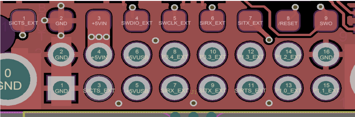
 Design with RFD900X in Cirkit Designer
Introduction
The RFD900X is a high-performance, long-range, low-power radio modem manufactured by RFDesign. Operating in the 902-928 MHz frequency band, this modem is designed for wireless data transmission in applications requiring reliable communication over extended distances. With a line-of-sight range of up to 100 km, the RFD900X is ideal for telemetry, remote control, and data logging in industrial, agricultural, and UAV systems.
Explore Projects Built with RFD900X
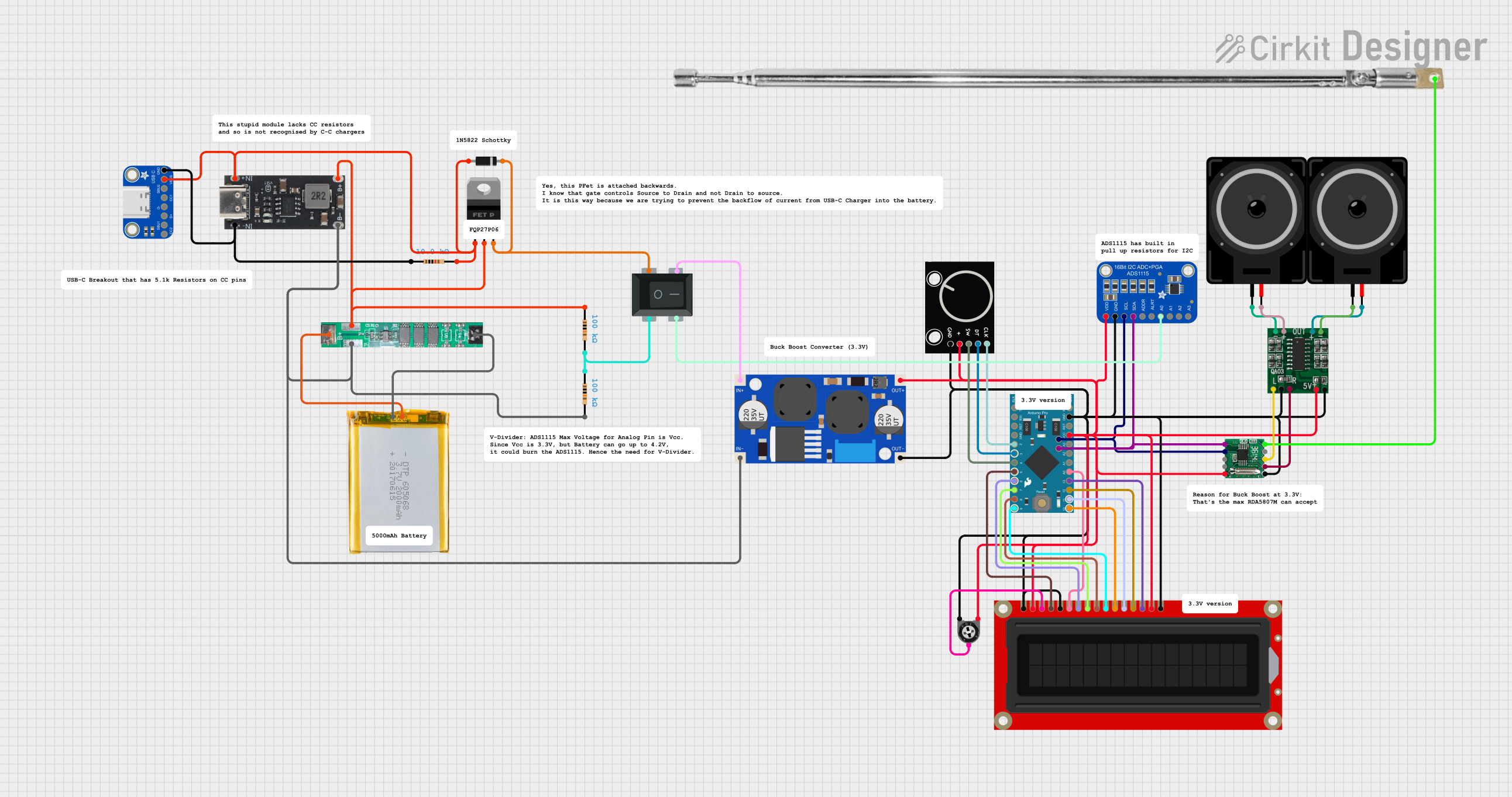 Open Project in Cirkit Designer
 Open Project in Cirkit Designer
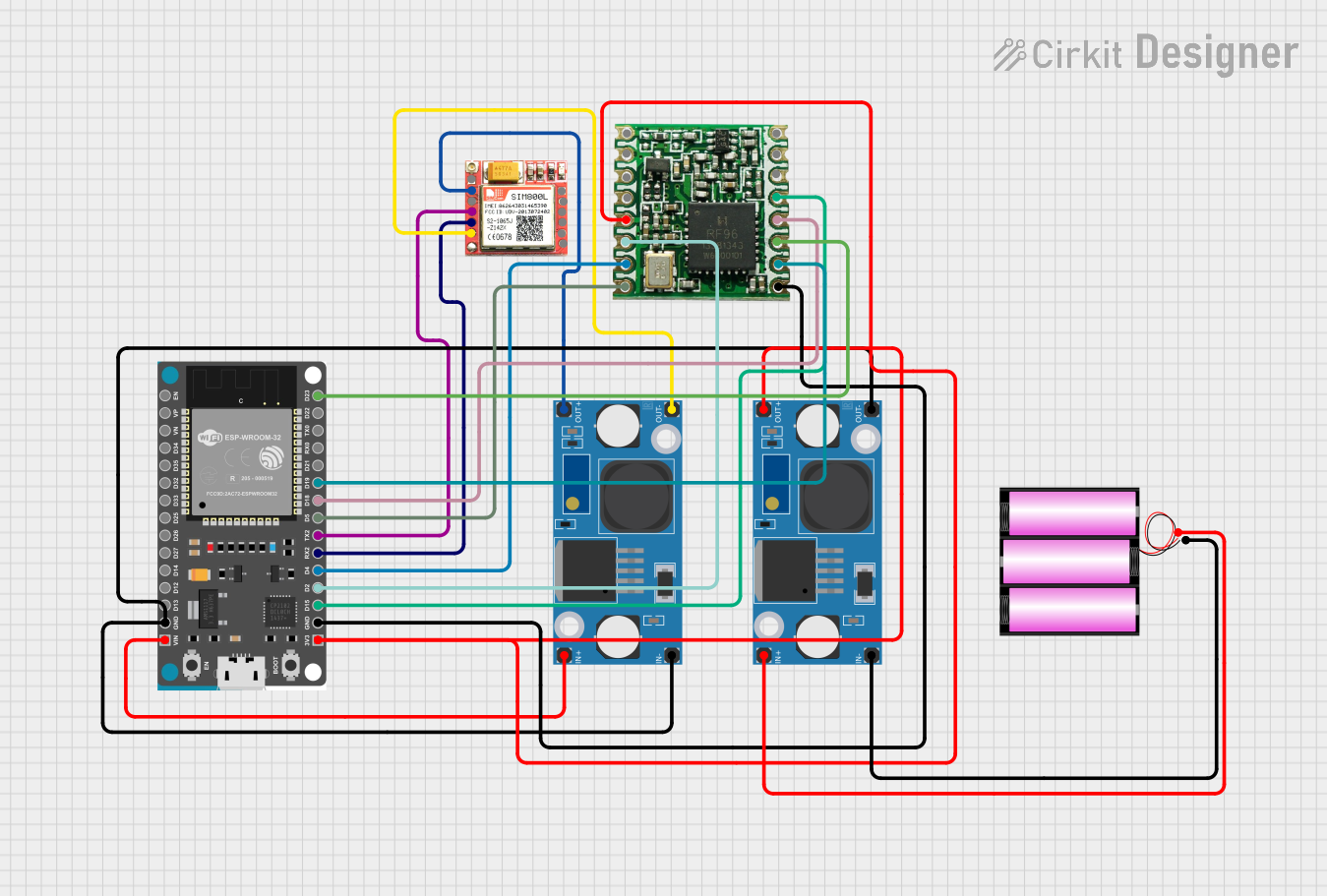 Open Project in Cirkit Designer
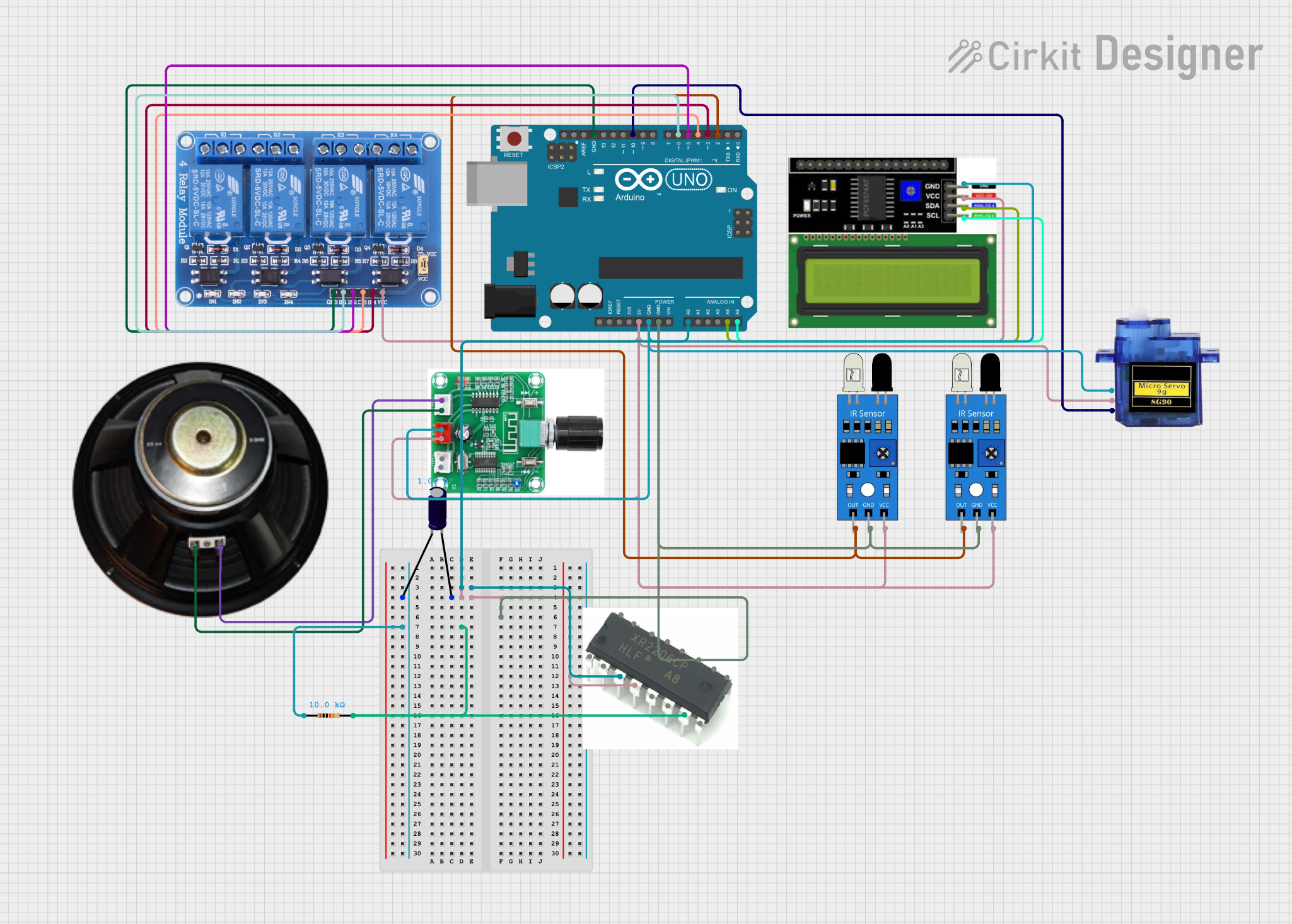 Open Project in Cirkit Designer
Explore Projects Built with RFD900X
Open Project in Cirkit DesignerOpen Project in Cirkit DesignerOpen Project in Cirkit DesignerOpen Project in Cirkit DesignerCommon Applications
- Telemetry: Real-time data transmission for monitoring and control.
- Unmanned Aerial Vehicles (UAVs): Long-range communication for drones.
- Remote Control Systems: Wireless control of devices over large distances.
- Data Logging: Collecting and transmitting sensor data in remote locations.
- Industrial Automation: Wireless communication in industrial environments.
Technical Specifications
Key Technical Details
| Parameter | Specification |
|---|---|
| Frequency Band | 902-928 MHz |
| Modulation | GFSK (Gaussian Frequency Shift Keying) |
| Transmit Power | Up to 1 W (30 dBm) |
| Receiver Sensitivity | -121 dBm |
| Data Rate | Up to 250 kbps |
| Range (Line of Sight) | Up to 100 km |
| Operating Voltage | 5 V |
| Current Consumption | 100 mA (typical) |
| Interface | UART (TTL level) |
| Dimensions | 30 mm x 57 mm x 12 mm |
| Operating Temperature | -40°C to +85°C |
Pin Configuration and Descriptions
The RFD900X features a 10-pin header for interfacing with external devices. Below is the pinout and description:
| Pin Number | Pin Name | Description |
|---|---|---|
| 1 | GND | Ground connection |
| 2 | VCC | Power supply input (5 V) |
| 3 | TX | UART Transmit (data output) |
| 4 | RX | UART Receive (data input) |
| 5 | RTS | Request to Send (flow control, optional) |
| 6 | CTS | Clear to Send (flow control, optional) |
| 7 | AUX | Auxiliary status indicator |
| 8 | CONFIG | Configuration mode input |
| 9 | RSSI | Received Signal Strength Indicator (analog out) |
| 10 | NC | Not Connected |
Usage Instructions
How to Use the RFD900X in a Circuit
- Power Supply: Connect the VCC pin to a regulated 5 V power source and the GND pin to ground.
- UART Communication: Connect the TX pin of the RFD900X to the RX pin of your microcontroller, and the RX pin of the RFD900X to the TX pin of your microcontroller.
- Optional Flow Control: If required, connect the RTS and CTS pins for hardware flow control.
- Antenna Connection: Attach a suitable 900 MHz antenna to the SMA connector for optimal performance.
- Configuration: To enter configuration mode, pull the CONFIG pin high during power-up. Use the provided configuration software to set parameters such as frequency, data rate, and transmit power.
Important Considerations
- Antenna Selection: Use a high-quality 900 MHz antenna to maximize range and signal quality.
- Power Supply: Ensure a stable 5 V power supply to avoid communication issues.
- Line of Sight: For maximum range, maintain a clear line of sight between the transmitter and receiver.
- Heat Dissipation: The RFD900X can generate heat during operation. Ensure adequate ventilation or heat sinking if used at high power levels.
Example: Connecting RFD900X to Arduino UNO
Below is an example of how to connect and use the RFD900X with an Arduino UNO for basic communication:
Wiring Diagram
| RFD900X Pin | Arduino UNO Pin |
|---|---|
| VCC | 5V |
| GND | GND |
| TX | Pin 10 (RX) |
| RX | Pin 11 (TX) |
Arduino Code
#include <SoftwareSerial.h>

// Define RX and TX pins for SoftwareSerial
SoftwareSerial rfd900x(10, 11); // RX = Pin 10, TX = Pin 11

void setup() {
  // Initialize serial communication with the RFD900X
  rfd900x.begin(57600); // Default baud rate for RFD900X
  Serial.begin(9600);   // Serial monitor for debugging

  Serial.println("RFD900X Communication Initialized");
}

void loop() {
  // Check if data is available from the RFD900X
  if (rfd900x.available()) {
    String receivedData = rfd900x.readString();
    Serial.print("Received: ");
    Serial.println(receivedData);
  }

  // Send data to the RFD900X
  if (Serial.available()) {
    String dataToSend = Serial.readString();
    rfd900x.println(dataToSend);
    Serial.print("Sent: ");
    Serial.println(dataToSend);
  }
}
Troubleshooting and FAQs
Common Issues and Solutions
No Communication Between Devices
- Cause: Incorrect wiring or baud rate mismatch.
- Solution: Double-check the wiring and ensure the baud rate matches the configuration of the RFD900X.
Limited Range
- Cause: Poor antenna quality or obstructions in the line of sight.
- Solution: Use a high-gain antenna and ensure a clear line of sight between devices.
Overheating
- Cause: Prolonged operation at maximum transmit power.
- Solution: Reduce the transmit power or improve heat dissipation with a heatsink.
Interference
- Cause: Other devices operating in the 900 MHz band.
- Solution: Change the frequency channel using the configuration software.
FAQs
Q: Can the RFD900X be used with 3.3 V systems?
- A: The RFD900X requires a 5 V power supply, but its UART pins are 3.3 V logic level compatible.
Q: How do I update the firmware?
- A: Use the RFDesign firmware update tool and follow the instructions provided in the user manual.
Q: What is the default baud rate of the RFD900X?
- A: The default baud rate is 57600 bps.
Q: Can I use multiple RFD900X modules in the same area?
- A: Yes, but ensure each module operates on a different frequency channel to avoid interference.
This concludes the documentation for the RFD900X. For further details, refer to the official RFDesign user manual.