
How to Use TRIAC: Examples, Pinouts, and Specs

 Design with TRIAC in Cirkit Designer
Introduction
A TRIAC (Triode for Alternating Current) is a three-terminal semiconductor device designed to control the flow of current in both directions. It is widely used in AC power control applications due to its ability to switch and regulate alternating current. Unlike a standard thyristor, which only conducts in one direction, the TRIAC can conduct in both halves of an AC cycle, making it highly versatile for controlling power in AC circuits.
Explore Projects Built with TRIAC
 Open Project in Cirkit Designer
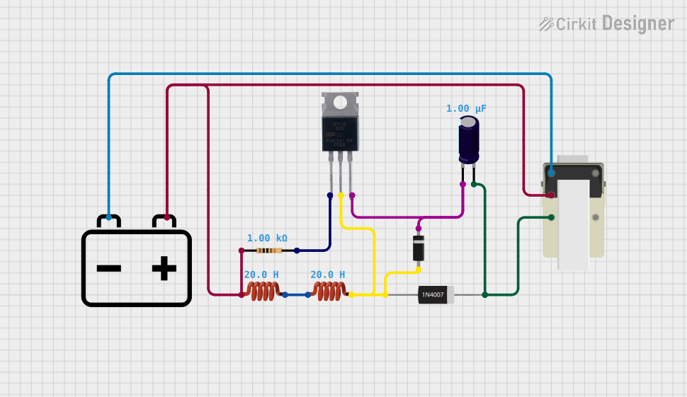 Open Project in Cirkit Designer
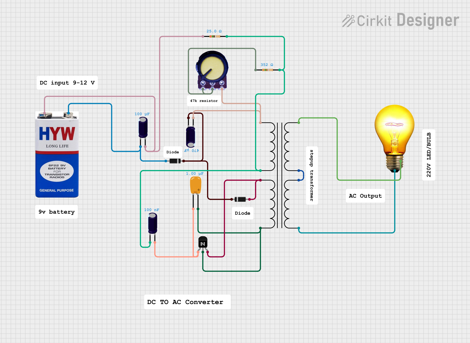 Open Project in Cirkit Designer
 Open Project in Cirkit Designer
Explore Projects Built with TRIAC
Open Project in Cirkit DesignerOpen Project in Cirkit DesignerOpen Project in Cirkit DesignerOpen Project in Cirkit DesignerCommon Applications and Use Cases
- Light dimmers
- Motor speed controllers
- Heating element control
- AC power switching
- Industrial automation systems
Technical Specifications
Below are the general technical specifications of a typical TRIAC. Note that specific values may vary depending on the model and manufacturer.
| Parameter | Description |
|---|---|
| Maximum Voltage (VDRM) | The maximum voltage the TRIAC can block in the off state (typically 400V to 800V). |
| Maximum Current (IT) | The maximum current the TRIAC can conduct in the on state (e.g., 4A, 8A, 16A). |
| Gate Trigger Voltage (VGT) | The minimum voltage required to trigger the TRIAC (typically 1V to 2.5V). |
| Gate Trigger Current (IGT) | The minimum current required to trigger the TRIAC (e.g., 5mA to 50mA). |
| Holding Current (IH) | The minimum current required to keep the TRIAC conducting (e.g., 10mA to 50mA). |
| Operating Temperature | The temperature range in which the TRIAC can operate (e.g., -40°C to 125°C). |
Pin Configuration and Descriptions
A TRIAC typically has three terminals: MT1, MT2, and Gate. Below is the pin configuration:
| Pin Name | Description |
|---|---|
| MT1 (Main Terminal 1) | One of the main current-carrying terminals. Connected to the load or AC source. |
| MT2 (Main Terminal 2) | The other main current-carrying terminal. Connected to the load or AC source. |
| Gate (G) | The control terminal. A small current applied here triggers the TRIAC to conduct. |
Usage Instructions
How to Use the TRIAC in a Circuit
Basic Circuit Setup:
- Connect MT1 and MT2 in series with the AC load and power source.
- Use a resistor to limit the current to the Gate terminal.
- Apply a triggering pulse to the Gate to turn the TRIAC on.
Gate Triggering:
- The TRIAC is triggered by a small current applied to the Gate terminal.
- The triggering pulse can be positive or negative, depending on the polarity of the AC cycle.
Snubber Circuit:
- To prevent false triggering due to voltage spikes, use a snubber circuit (a resistor and capacitor in series) across the TRIAC.
Heat Dissipation:
- Ensure proper heat dissipation by using a heatsink if the TRIAC is handling high currents.
Example: Controlling a Lamp with an Arduino UNO
Below is an example of how to use a TRIAC to control an AC lamp with an Arduino UNO.
Circuit Components:
- TRIAC (e.g., BT136)
- Optocoupler (e.g., MOC3021) for isolation
- Resistors (330Ω, 10kΩ)
- AC lamp
- Arduino UNO
Code Example:
// TRIAC Control Example with Arduino UNO
// This code demonstrates how to control an AC lamp using a TRIAC and an optocoupler.

const int triacPin = 3; // Pin connected to the optocoupler's input

void setup() {
  pinMode(triacPin, OUTPUT); // Set the TRIAC control pin as output
}

void loop() {
  digitalWrite(triacPin, HIGH); // Turn on the TRIAC (lamp ON)
  delay(1000);                  // Keep the lamp ON for 1 second
  digitalWrite(triacPin, LOW);  // Turn off the TRIAC (lamp OFF)
  delay(1000);                  // Keep the lamp OFF for 1 second
}
Important Considerations and Best Practices
- Always use an optocoupler for isolation when interfacing a TRIAC with a microcontroller.
- Ensure the TRIAC's voltage and current ratings exceed the requirements of your load.
- Use a snubber circuit to protect the TRIAC from voltage transients.
- Avoid exceeding the Gate trigger current to prevent damage to the TRIAC.
Troubleshooting and FAQs
Common Issues and Solutions
TRIAC Does Not Turn On:
- Check if the Gate trigger voltage and current are sufficient.
- Verify the connections to MT1, MT2, and Gate.
TRIAC Turns On Unexpectedly:
- Ensure proper isolation between the control circuit and the AC load.
- Add a snubber circuit to suppress voltage spikes.
TRIAC Overheats:
- Check if the load current exceeds the TRIAC's maximum current rating.
- Use a heatsink to dissipate heat effectively.
Flickering in AC Load:
- Verify the stability of the Gate triggering signal.
- Ensure the snubber circuit is correctly designed.
FAQs
Q1: Can a TRIAC be used for DC circuits?
A1: No, a TRIAC is designed for AC circuits. It cannot turn off in a DC circuit because it relies on the AC zero-crossing point to stop conducting.
Q2: How do I calculate the resistor value for the Gate?
A2: Use Ohm's law: ( R = \frac{V_{control} - V_{GT}}{I_{GT}} ), where ( V_{control} ) is the control voltage, ( V_{GT} ) is the Gate trigger voltage, and ( I_{GT} ) is the Gate trigger current.
Q3: What is the difference between a TRIAC and an SCR?
A3: A TRIAC can conduct in both directions, making it suitable for AC applications. An SCR (Silicon Controlled Rectifier) conducts in only one direction and is typically used in DC circuits.