Cirkit Designer Logo
Cirkit Designer
Your all-in-one circuit design IDE
Home / 
Component Documentation

How to Use LM2596S-Switching Voltage Regulators 150 KHZ 3A STEP-DOWN VLTG REG: Examples, Pinouts, and Specs

Image of LM2596S-Switching Voltage Regulators 150 KHZ 3A STEP-DOWN VLTG REG
Cirkit Designer LogoDesign with LM2596S-Switching Voltage Regulators 150 KHZ 3A STEP-DOWN VLTG REG in Cirkit Designer

Introduction

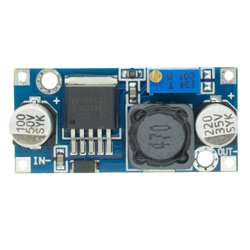
The LM2596S-ADJ/NOPB is a high-efficiency switching voltage regulator manufactured by Texas Instruments. It operates at a frequency of 150 kHz and is capable of delivering up to 3A of output current. This component is designed for step-down (buck) voltage regulation applications, making it ideal for converting higher input voltages to lower, stable output voltages.

Explore Projects Built with LM2596S-Switching Voltage Regulators 150 KHZ 3A STEP-DOWN VLTG REG

Use Cirkit Designer to design, explore, and prototype these projects online. Some projects support real-time simulation. Click "Open Project" to start designing instantly!
LM317 Voltage Regulator Circuit for Adjustable Power Supply with Transformer and Diodes
Image of 12V BULB LIGHT DIMMER CIRCUIT: A project utilizing LM2596S-Switching Voltage Regulators 150 KHZ 3A STEP-DOWN VLTG REG in a practical application
This circuit is a regulated power supply that converts AC voltage to a stable DC voltage. It uses a transformer to step down the AC voltage, diodes for rectification, an electrolytic capacitor for smoothing, and an LM317 voltage regulator to provide a stable output voltage, which is adjustable via a potentiometer. The output powers a bulb.
Cirkit Designer LogoOpen Project in Cirkit Designer
Battery-Powered UPS with Step-Down Buck Converter and BMS
Image of Mini ups: A project utilizing LM2596S-Switching Voltage Regulators 150 KHZ 3A STEP-DOWN VLTG REG in a practical application
This circuit is a power management system that steps down a 240V AC input to a lower DC voltage using a buck converter, which then powers a 40W UPS. The UPS is controlled by a rocker switch and is backed up by a battery management system (BMS) connected to three 3.7V batteries in series, ensuring continuous power supply.
Cirkit Designer LogoOpen Project in Cirkit Designer
Battery-Powered Adjustable Voltage Regulator with Li-ion 18650 Batteries and BMS
Image of mini ups: A project utilizing LM2596S-Switching Voltage Regulators 150 KHZ 3A STEP-DOWN VLTG REG in a practical application
This circuit is a power management system that uses four Li-ion 18650 batteries connected to a 2S 30A BMS for battery management and protection. The system includes step-up and step-down voltage regulators to provide adjustable output voltages, controlled by a rocker switch, and multiple DC jacks for power input and output.
Cirkit Designer LogoOpen Project in Cirkit Designer
AC to DC Power Supply with Voltage Regulation and LED Indicator
Image of Copy of 8 volt AC to DC convertor (1): A project utilizing LM2596S-Switching Voltage Regulators 150 KHZ 3A STEP-DOWN VLTG REG in a practical application
This circuit is a basic AC to DC power supply with voltage regulation. It includes a transformer to step down the AC voltage, a bridge rectifier made of 1N4007 diodes to convert AC to DC, an electrolytic capacitor for smoothing, and a voltage regulator to provide a stable DC output. An LED with a current-limiting resistor indicates the presence of the output voltage.
Cirkit Designer LogoOpen Project in Cirkit Designer

Explore Projects Built with LM2596S-Switching Voltage Regulators 150 KHZ 3A STEP-DOWN VLTG REG

Use Cirkit Designer to design, explore, and prototype these projects online. Some projects support real-time simulation. Click "Open Project" to start designing instantly!
Image of 12V BULB LIGHT DIMMER CIRCUIT: A project utilizing LM2596S-Switching Voltage Regulators 150 KHZ 3A STEP-DOWN VLTG REG in a practical application
LM317 Voltage Regulator Circuit for Adjustable Power Supply with Transformer and Diodes
This circuit is a regulated power supply that converts AC voltage to a stable DC voltage. It uses a transformer to step down the AC voltage, diodes for rectification, an electrolytic capacitor for smoothing, and an LM317 voltage regulator to provide a stable output voltage, which is adjustable via a potentiometer. The output powers a bulb.
Cirkit Designer LogoOpen Project in Cirkit Designer
Image of Mini ups: A project utilizing LM2596S-Switching Voltage Regulators 150 KHZ 3A STEP-DOWN VLTG REG in a practical application
Battery-Powered UPS with Step-Down Buck Converter and BMS
This circuit is a power management system that steps down a 240V AC input to a lower DC voltage using a buck converter, which then powers a 40W UPS. The UPS is controlled by a rocker switch and is backed up by a battery management system (BMS) connected to three 3.7V batteries in series, ensuring continuous power supply.
Cirkit Designer LogoOpen Project in Cirkit Designer
Image of mini ups: A project utilizing LM2596S-Switching Voltage Regulators 150 KHZ 3A STEP-DOWN VLTG REG in a practical application
Battery-Powered Adjustable Voltage Regulator with Li-ion 18650 Batteries and BMS
This circuit is a power management system that uses four Li-ion 18650 batteries connected to a 2S 30A BMS for battery management and protection. The system includes step-up and step-down voltage regulators to provide adjustable output voltages, controlled by a rocker switch, and multiple DC jacks for power input and output.
Cirkit Designer LogoOpen Project in Cirkit Designer
Image of Copy of 8 volt AC to DC convertor (1): A project utilizing LM2596S-Switching Voltage Regulators 150 KHZ 3A STEP-DOWN VLTG REG in a practical application
AC to DC Power Supply with Voltage Regulation and LED Indicator
This circuit is a basic AC to DC power supply with voltage regulation. It includes a transformer to step down the AC voltage, a bridge rectifier made of 1N4007 diodes to convert AC to DC, an electrolytic capacitor for smoothing, and a voltage regulator to provide a stable DC output. An LED with a current-limiting resistor indicates the presence of the output voltage.
Cirkit Designer LogoOpen Project in Cirkit Designer

Common Applications and Use Cases

  • Power Supply Units: Used in power supply circuits to provide stable voltage to various electronic devices.
  • Battery-Powered Devices: Ideal for extending battery life by efficiently converting battery voltage to the required levels.
  • Embedded Systems: Commonly used in microcontroller-based projects, including Arduino, to provide regulated power.
  • Industrial Automation: Used in control systems and automation equipment to ensure reliable power delivery.

Technical Specifications

Key Technical Details

Parameter Value
Input Voltage Range 4.5V to 40V
Output Voltage Range 1.23V to 37V (adjustable)
Output Current Up to 3A
Switching Frequency 150 kHz
Efficiency Up to 90%
Operating Temperature -40°C to +125°C
Package Type TO-263-5

Pin Configuration and Descriptions

Pin Number Pin Name Description
1 VIN Input voltage (4.5V to 40V)
2 Output Regulated output voltage (1.23V to 37V)
3 Ground Ground connection
4 Feedback Feedback input for adjusting output voltage
5 ON/OFF Enable/disable control (active low)

Usage Instructions

How to Use the LM2596S-ADJ/NOPB in a Circuit

  1. Input Capacitor (CIN): Connect a low ESR capacitor (e.g., 100µF) between VIN and Ground to filter input voltage.
  2. Output Capacitor (COUT): Connect a low ESR capacitor (e.g., 220µF) between Output and Ground to stabilize the output voltage.
  3. Inductor (L): Choose an inductor with appropriate current rating (e.g., 33µH) to smooth the output current.
  4. Feedback Resistors (R1, R2): Use a voltage divider network to set the desired output voltage. The output voltage ( V_{OUT} ) can be calculated using the formula: [ V_{OUT} = 1.23 \times \left(1 + \frac{R1}{R2}\right) ]
  5. ON/OFF Control: Connect the ON/OFF pin to ground to enable the regulator. Leave it floating or connect to VIN to disable.

Important Considerations and Best Practices

  • Thermal Management: Ensure adequate heat dissipation by using a heatsink or proper PCB layout to avoid overheating.
  • Component Selection: Use low ESR capacitors and inductors with appropriate current ratings to ensure stable operation.
  • PCB Layout: Minimize the length of high-current paths and place input/output capacitors close to the regulator pins to reduce noise and improve performance.

Example Circuit with Arduino UNO

Below is an example of how to use the LM2596S-ADJ/NOPB to power an Arduino UNO with a 5V output:

/*
 * Example code to read analog input from a sensor and print the value
 * to the serial monitor. The LM2596S-ADJ/NOPB is used to provide a
 * stable 5V output to power the Arduino UNO.
 */

const int sensorPin = A0; // Analog input pin for the sensor
int sensorValue = 0;      // Variable to store the sensor value

void setup() {
  Serial.begin(9600); // Initialize serial communication at 9600 baud
}

void loop() {
  sensorValue = analogRead(sensorPin); // Read the analog input
  Serial.print("Sensor Value: ");
  Serial.println(sensorValue); // Print the sensor value to the serial monitor
  delay(1000); // Wait for 1 second before the next reading
}

Troubleshooting and FAQs

Common Issues and Solutions

  1. No Output Voltage:

    • Solution: Check the input voltage and ensure it is within the specified range (4.5V to 40V). Verify that the ON/OFF pin is connected to ground to enable the regulator.
  2. Overheating:

    • Solution: Ensure proper heat dissipation by using a heatsink or improving PCB layout. Check for excessive load current and reduce if necessary.
  3. Output Voltage Instability:

    • Solution: Use low ESR capacitors for input and output filtering. Verify the feedback resistor values and connections.

FAQs

  1. Can I use the LM2596S-ADJ/NOPB to power a 3.3V device?

    • Yes, you can adjust the output voltage to 3.3V using the appropriate feedback resistor values.
  2. What is the maximum input voltage for the LM2596S-ADJ/NOPB?

    • The maximum input voltage is 40V.
  3. How do I calculate the output voltage?

    • Use the formula ( V_{OUT} = 1.23 \times \left(1 + \frac{R1}{R2}\right) ) to calculate the output voltage based on the feedback resistor values.

By following this documentation, users can effectively utilize the LM2596S-ADJ/NOPB switching voltage regulator in their projects, ensuring efficient and stable power delivery.