How to Use Camera Module IMX307: Examples, Pinouts, and Specs
Introduction
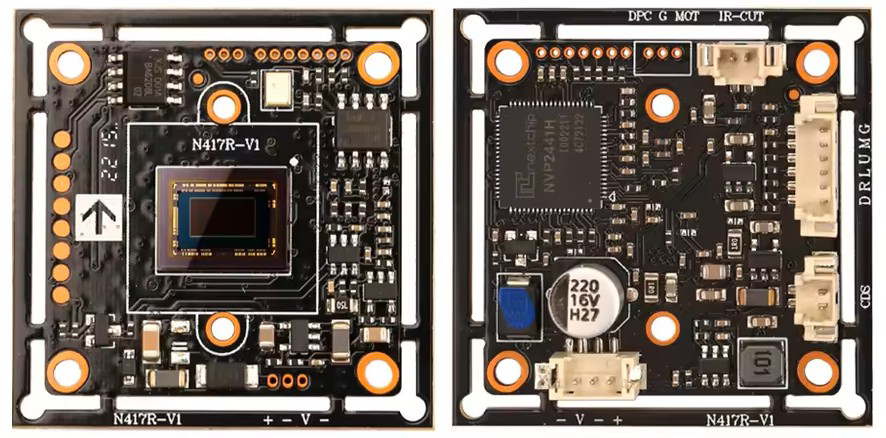
The IMX307 is a high-performance image sensor module designed for capturing high-quality images and videos, even in low-light conditions. It features a 1/2.8-inch optical format and a resolution of 2.1 megapixels, delivering sharp and detailed visuals. The module incorporates advanced technologies such as HDR (High Dynamic Range) imaging and low noise levels, ensuring excellent performance in challenging lighting environments.
Explore Projects Built with Camera Module IMX307
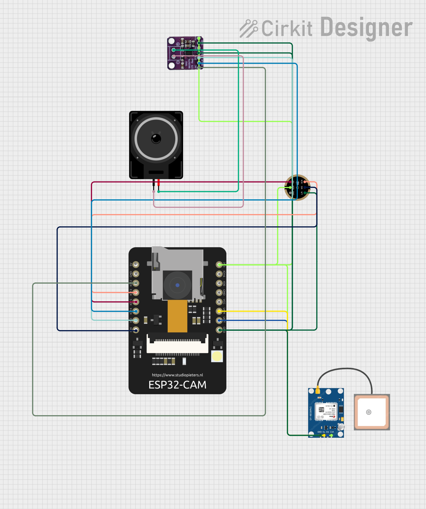


Explore Projects Built with Camera Module IMX307
Common Applications and Use Cases
- Surveillance Systems: Ideal for security cameras requiring clear images in low-light or nighttime conditions.
- Automotive Applications: Used in advanced driver-assistance systems (ADAS) and dash cameras for enhanced visibility.
- Industrial Applications: Suitable for machine vision, robotics, and quality control systems.
- Consumer Electronics: Can be integrated into smart home devices and IoT cameras.
Technical Specifications
Key Technical Details
| Parameter | Value |
|---|---|
| Optical Format | 1/2.8 inch |
| Resolution | 2.1 Megapixels (1920 x 1080) |
| Pixel Size | 2.9 µm x 2.9 µm |
| Frame Rate | Up to 60 fps (Full HD) |
| Dynamic Range | High Dynamic Range (HDR) |
| Sensitivity | Excellent low-light performance |
| Interface | MIPI CSI-2 |
| Supply Voltage | 2.8V (Analog), 1.2V (Digital) |
| Operating Temperature | -30°C to +85°C |
| Shutter Type | Rolling Shutter |
Pin Configuration and Descriptions
| Pin Name | Type | Description |
|---|---|---|
| VDD_ANA | Power | Analog power supply (2.8V). |
| VDD_DIG | Power | Digital power supply (1.2V). |
| GND | Ground | Ground connection. |
| MIPI_D0+ | Differential | MIPI CSI-2 data lane 0 (positive). |
| MIPI_D0- | Differential | MIPI CSI-2 data lane 0 (negative). |
| MIPI_CLK+ | Differential | MIPI CSI-2 clock lane (positive). |
| MIPI_CLK- | Differential | MIPI CSI-2 clock lane (negative). |
| SDA | I2C Data | I2C data line for configuration. |
| SCL | I2C Clock | I2C clock line for configuration. |
| RESET | Input | Active-low reset signal. |
| PWDN | Input | Power-down control (active high). |
Usage Instructions
How to Use the IMX307 in a Circuit
- Power Supply: Connect the analog power supply (2.8V) to the
VDD_ANApin and the digital power supply (1.2V) to theVDD_DIGpin. Ensure proper decoupling capacitors are used to minimize noise. - Grounding: Connect all ground pins (
GND) to a common ground plane to ensure stable operation. - MIPI CSI-2 Interface: Connect the MIPI data and clock lanes (
MIPI_D0+,MIPI_D0-,MIPI_CLK+,MIPI_CLK-) to the corresponding MIPI CSI-2 interface on your processor or microcontroller. - I2C Configuration: Use the
SDAandSCLpins to configure the sensor via I2C. The default I2C address is typically 0x34 (check the datasheet for confirmation). - Reset and Power-Down: Use the
RESETpin to initialize the sensor and thePWDNpin to control power-saving modes.
Important Considerations and Best Practices
- Low-Light Optimization: Leverage the HDR feature and adjust gain settings via I2C for optimal performance in low-light conditions.
- Clock Signal Integrity: Ensure proper impedance matching for the MIPI clock and data lanes to avoid signal degradation.
- Thermal Management: If used in high-temperature environments, consider adding a heat sink or thermal pad to maintain performance.
- Lens Selection: Pair the IMX307 with a high-quality lens to fully utilize its 2.1 MP resolution and low-light capabilities.
Example: Connecting IMX307 to an Arduino UNO
The IMX307 requires a processor with a MIPI CSI-2 interface, which the Arduino UNO does not natively support. However, you can use an external MIPI-to-SPI or MIPI-to-parallel bridge to interface the IMX307 with the Arduino UNO. Below is an example of configuring the IMX307 via I2C using the Arduino Wire library:
#include <Wire.h>

#define IMX307_I2C_ADDRESS 0x34  // Default I2C address of the IMX307

void setup() {
  Wire.begin();  // Initialize I2C communication
  Serial.begin(9600);  // Start serial communication for debugging

  // Reset the IMX307
  pinMode(7, OUTPUT);  // Assume RESET pin is connected to Arduino pin 7
  digitalWrite(7, LOW);  // Hold RESET low
  delay(10);  // Wait for 10ms
  digitalWrite(7, HIGH);  // Release RESET
  delay(100);  // Wait for the sensor to initialize

  // Configure the IMX307 via I2C
  configureIMX307();
}

void loop() {
  // Main loop can include image capture or further configuration
}

void configureIMX307() {
  Wire.beginTransmission(IMX307_I2C_ADDRESS);
  // Example: Write to a hypothetical register (0x01) to enable HDR mode
  Wire.write(0x01);  // Register address
  Wire.write(0x01);  // Data to enable HDR
  Wire.endTransmission();

  Serial.println("IMX307 configured for HDR mode.");
}
Troubleshooting and FAQs
Common Issues and Solutions
No Image Output:
- Cause: Incorrect MIPI CSI-2 connection or configuration.
- Solution: Verify the MIPI data and clock connections. Check the I2C configuration to ensure the sensor is initialized correctly.
I2C Communication Failure:
- Cause: Incorrect I2C address or wiring.
- Solution: Confirm the I2C address of the IMX307 and ensure proper pull-up resistors are used on the
SDAandSCLlines.
Poor Image Quality:
- Cause: Incorrect lens or improper gain settings.
- Solution: Use a high-quality lens and adjust the gain and exposure settings via I2C.
Overheating:
- Cause: Prolonged operation in high-temperature environments.
- Solution: Add a heat sink or improve ventilation around the module.
FAQs
Can the IMX307 be used with Raspberry Pi? Yes, the IMX307 can be interfaced with Raspberry Pi models that support the MIPI CSI-2 interface, such as the Raspberry Pi 4. A compatible driver may be required.
What is the maximum frame rate supported? The IMX307 supports up to 60 frames per second (fps) at full HD resolution (1920 x 1080).
Does the IMX307 support global shutter? No, the IMX307 uses a rolling shutter, which is suitable for most applications but may introduce motion artifacts in high-speed scenarios.