How to Use Solar Inverter DC TO AC: Examples, Pinouts, and Specs
Introduction
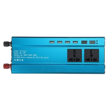
The Solaric UNA Solar Inverter is a high-efficiency device designed to convert direct current (DC) generated by solar panels into alternating current (AC) suitable for use in homes and businesses. This inverter is essential for integrating solar power systems into the electrical grid or for standalone applications. It ensures that the energy harnessed from the sun can be used to power household appliances, industrial equipment, and other electrical devices.
Explore Projects Built with Solar Inverter DC TO AC
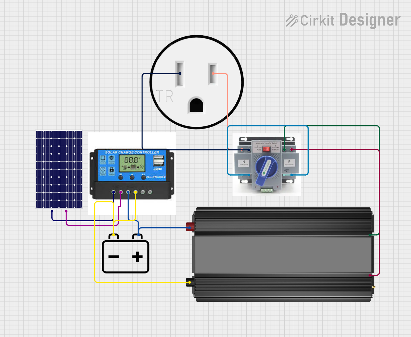

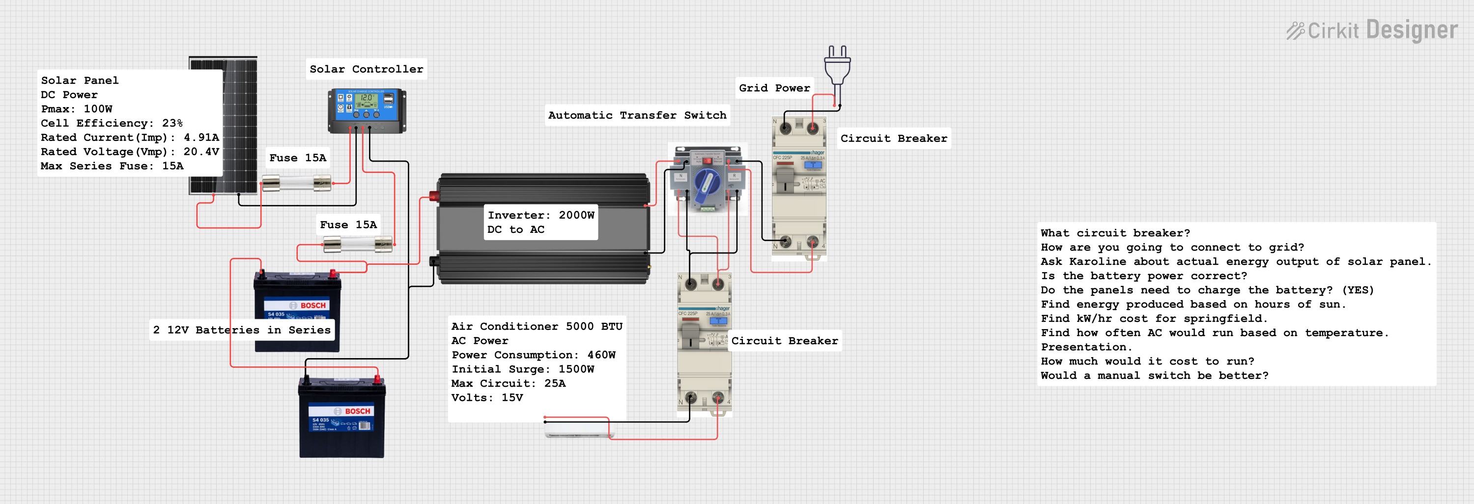
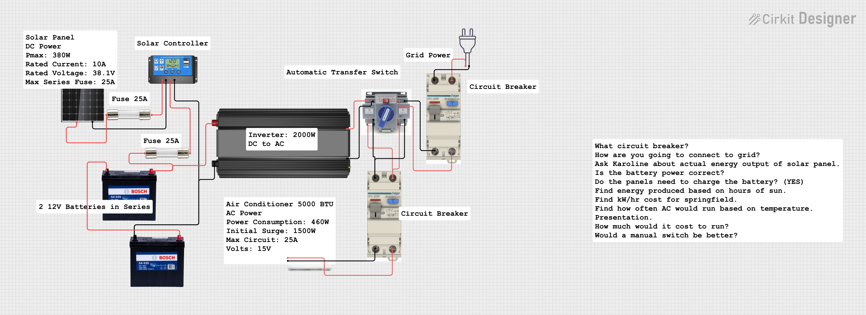
Explore Projects Built with Solar Inverter DC TO AC
Common Applications and Use Cases
- Residential solar power systems
- Commercial solar installations
- Off-grid solar power systems
- Backup power solutions
- Renewable energy projects
Technical Specifications
Key Technical Details
| Parameter | Value |
|---|---|
| Input Voltage Range | 12V - 48V DC |
| Output Voltage | 110V/220V AC ± 5% |
| Output Frequency | 50Hz/60Hz ± 1% |
| Output Power | 1000W, 2000W, 3000W options |
| Efficiency | Up to 95% |
| Total Harmonic Distortion | < 3% |
| Operating Temperature | -10°C to 50°C |
| Cooling Method | Forced air cooling |
| Dimensions | 350mm x 200mm x 100mm |
| Weight | 5kg |
Pin Configuration and Descriptions
| Pin Number | Pin Name | Description |
|---|---|---|
| 1 | DC+ | Positive DC input from solar panels |
| 2 | DC- | Negative DC input from solar panels |
| 3 | AC Output L | Live wire for AC output |
| 4 | AC Output N | Neutral wire for AC output |
| 5 | Ground | Ground connection for safety |
| 6 | Remote Control | Remote control input for on/off functionality |
| 7 | Status LED | LED indicator for operational status |
Usage Instructions
How to Use the Component in a Circuit
Connect the Solar Panels:
- Connect the positive terminal of the solar panel to the DC+ pin of the inverter.
- Connect the negative terminal of the solar panel to the DC- pin of the inverter.
Connect the AC Output:
- Connect the AC Output L pin to the live wire of the load or electrical grid.
- Connect the AC Output N pin to the neutral wire of the load or electrical grid.
Grounding:
- Connect the Ground pin to a suitable earth ground to ensure safety and reduce electrical noise.
Remote Control (Optional):
- If remote control functionality is required, connect a switch or control circuit to the Remote Control pin.
Power On:
- Ensure all connections are secure and correct.
- Turn on the inverter using the power switch or remote control.
Important Considerations and Best Practices
- Safety First: Always ensure the inverter is properly grounded to prevent electrical shocks.
- Correct Sizing: Ensure the inverter's power rating matches the load requirements to avoid overloading.
- Ventilation: Install the inverter in a well-ventilated area to prevent overheating.
- Regular Maintenance: Periodically check connections and clean the inverter to maintain optimal performance.
Troubleshooting and FAQs
Common Issues Users Might Face
Inverter Not Turning On:
- Solution: Check the DC input connections and ensure the solar panels are providing sufficient voltage. Verify the remote control switch is in the correct position.
No AC Output:
- Solution: Ensure the AC output connections are correct. Check if the inverter is in standby mode and switch it to active mode.
Overheating:
- Solution: Ensure the inverter is installed in a well-ventilated area. Check for any obstructions to the cooling fans and clean them if necessary.
Low Efficiency:
- Solution: Verify that the input voltage is within the specified range. Ensure the load is within the inverter's power rating.
Solutions and Tips for Troubleshooting
- LED Indicators: Use the status LED to diagnose issues. Refer to the user manual for LED indicator meanings.
- Regular Inspections: Periodically inspect all connections and the inverter's physical condition.
- Firmware Updates: Check for firmware updates from Solaric to ensure the inverter operates with the latest features and improvements.
Example Code for Arduino UNO Integration
If you are using the Solaric UNA Solar Inverter with an Arduino UNO for monitoring purposes, you can use the following example code to read the inverter's status via the remote control pin.
// Example code to read the status of the Solaric UNA Solar Inverter
// using an Arduino UNO. The remote control pin is connected to
// digital pin 2 on the Arduino.

const int remoteControlPin = 2; // Remote control pin connected to pin 2
const int ledPin = 13;          // Onboard LED for status indication

void setup() {
  pinMode(remoteControlPin, INPUT); // Set remote control pin as input
  pinMode(ledPin, OUTPUT);          // Set LED pin as output
  Serial.begin(9600);               // Initialize serial communication
}

void loop() {
  int inverterStatus = digitalRead(remoteControlPin); // Read inverter status

  if (inverterStatus == HIGH) {
    digitalWrite(ledPin, HIGH); // Turn on LED if inverter is on
    Serial.println("Inverter is ON");
  } else {
    digitalWrite(ledPin, LOW);  // Turn off LED if inverter is off
    Serial.println("Inverter is OFF");
  }

  delay(1000); // Wait for 1 second before next reading
}
This code reads the status of the inverter and indicates it using the onboard LED of the Arduino UNO. The status is also printed to the serial monitor for easy monitoring.
By following this documentation, users can effectively integrate and troubleshoot the Solaric UNA Solar Inverter in their solar power systems, ensuring reliable and efficient energy conversion.