How to Use Raspberry Pi 3 A+: Examples, Pinouts, and Specs
Introduction
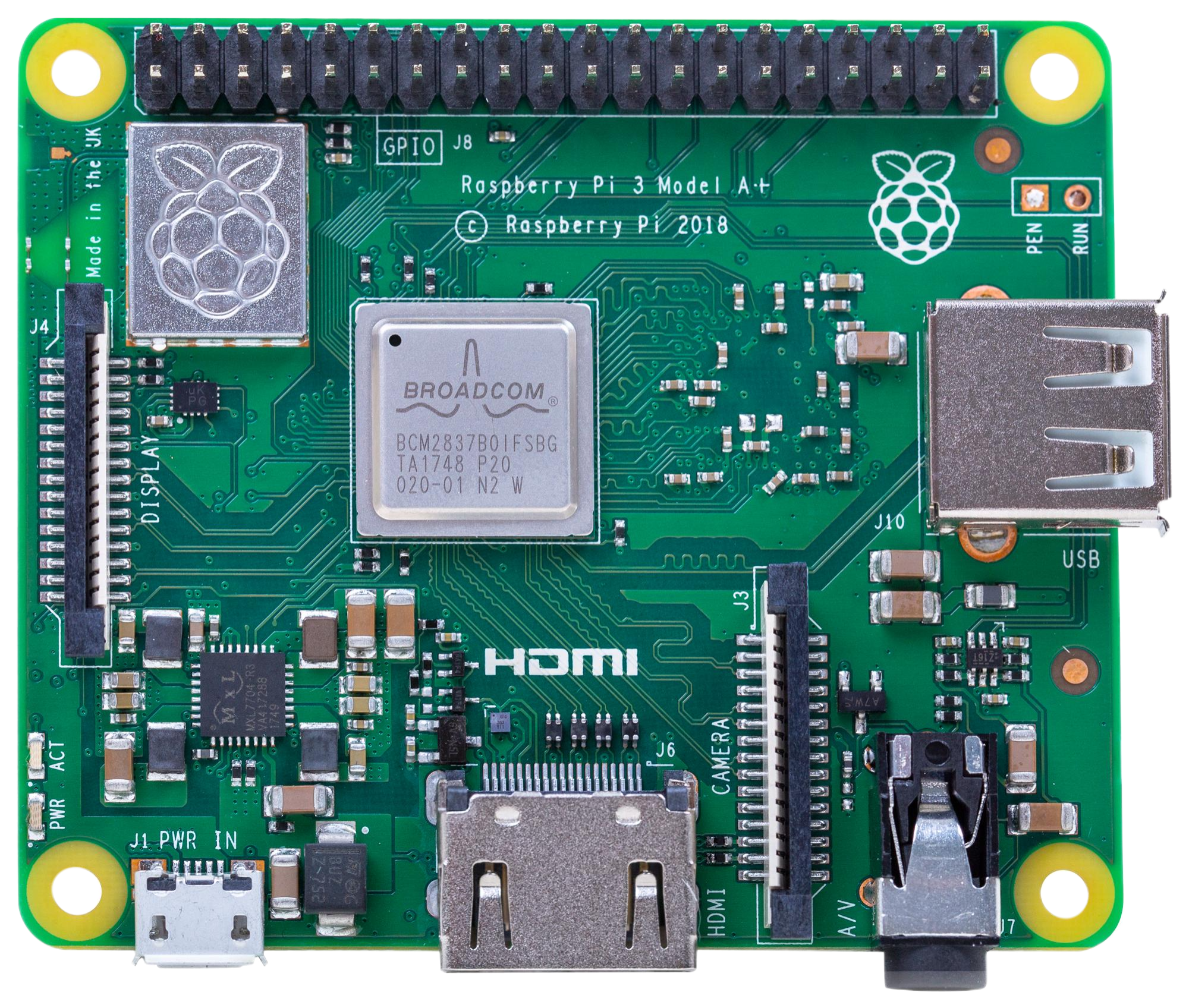
The Raspberry Pi 3 Model A+ is a compact, low-cost single-board computer developed by Raspberry Pi. It features a quad-core ARM Cortex-A53 processor, 1GB of RAM, and a variety of connectivity options, making it an excellent choice for DIY electronics projects, programming, and learning about computing. Its small form factor and energy efficiency make it ideal for embedded systems, IoT applications, and portable devices.
Explore Projects Built with Raspberry Pi 3 A+
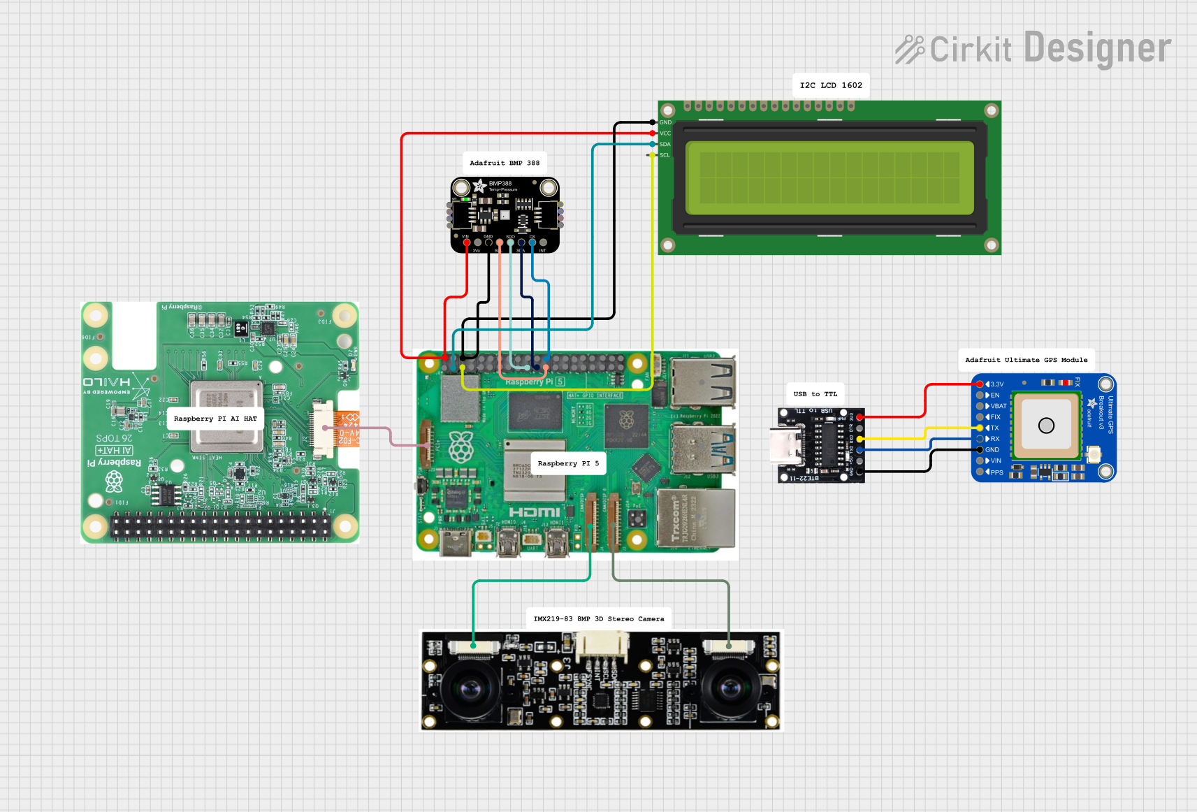
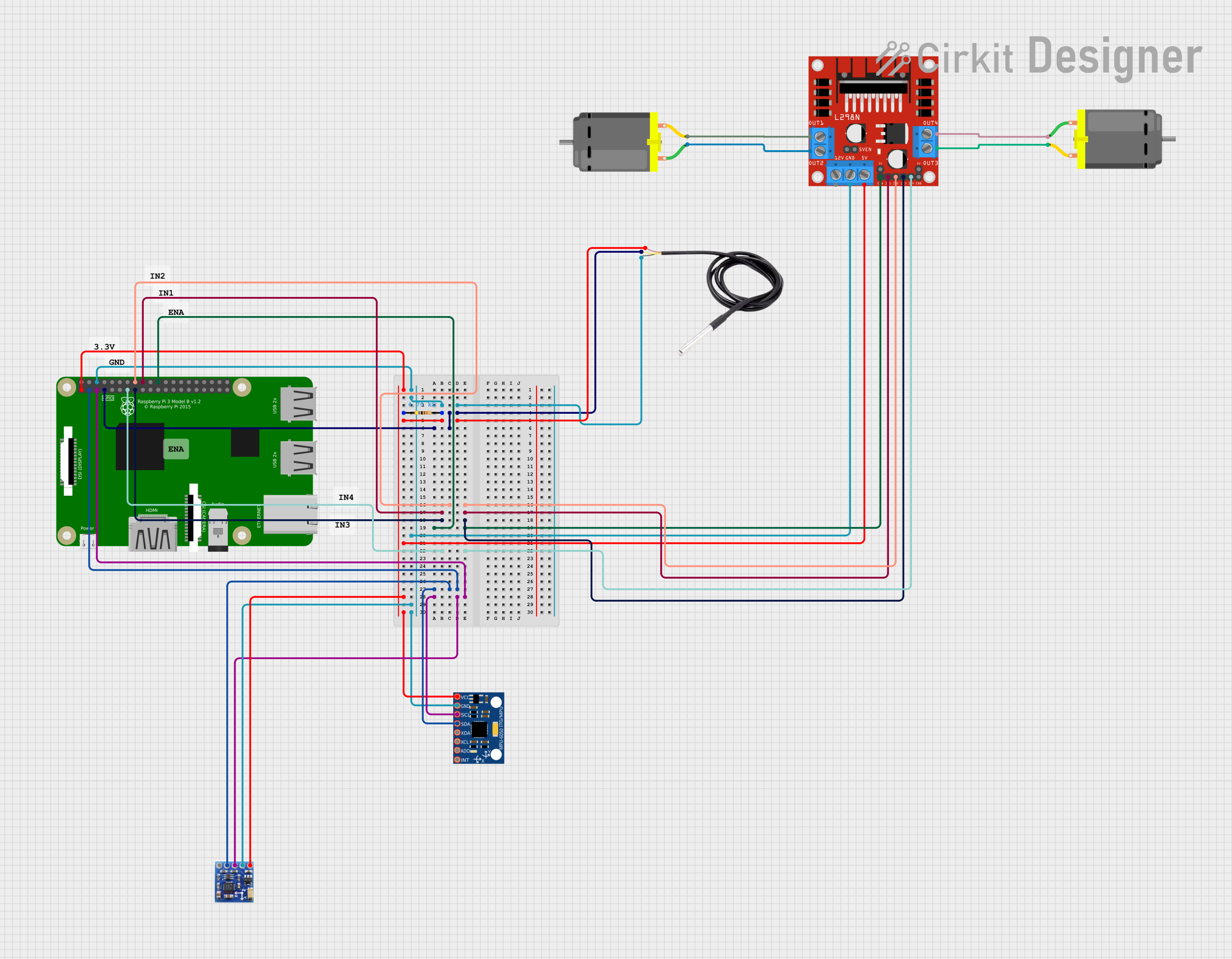
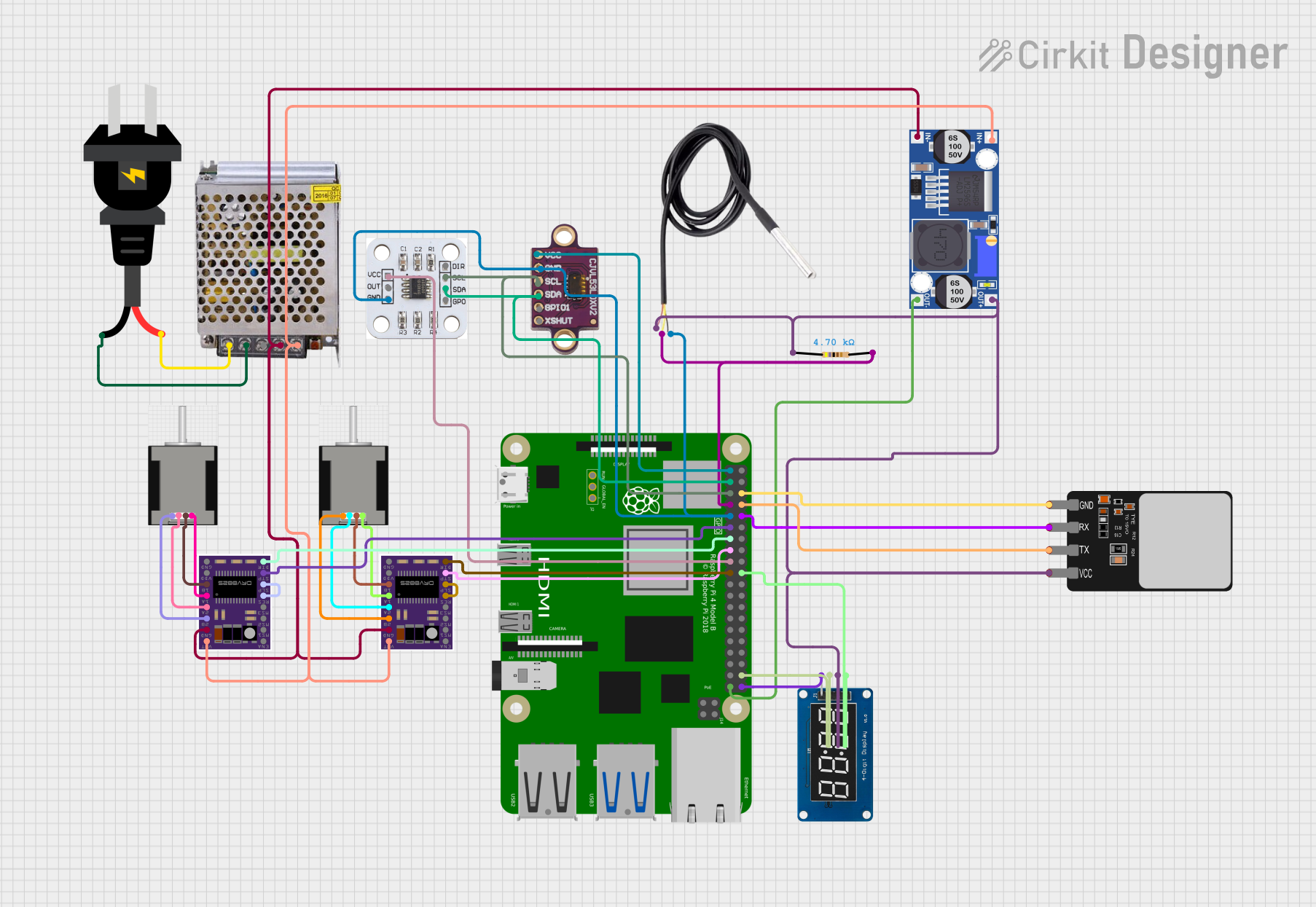

Explore Projects Built with Raspberry Pi 3 A+
Common Applications and Use Cases
- DIY electronics and robotics projects
- IoT (Internet of Things) devices
- Media centers and streaming devices
- Educational tools for learning programming and hardware
- Home automation systems
- Lightweight web servers
Technical Specifications
Below are the key technical details of the Raspberry Pi 3 Model A+:
| Specification | Details |
|---|---|
| Processor | Quad-core ARM Cortex-A53, 1.4GHz |
| RAM | 1GB LPDDR2 SDRAM |
| Wireless Connectivity | 2.4GHz and 5GHz IEEE 802.11b/g/n/ac Wi-Fi, Bluetooth 4.2, BLE |
| GPIO Pins | 40-pin GPIO header (fully compatible with previous Raspberry Pi models) |
| USB Ports | 1x USB 2.0 |
| HDMI Output | Full-size HDMI |
| Audio | Combined 3.5mm audio jack and composite video |
| Storage | MicroSD card slot |
| Power Supply | 5V/2.5A via micro-USB or GPIO header |
| Dimensions | 65mm x 56mm x 12mm |
| Weight | 29g |
Pin Configuration and Descriptions
The Raspberry Pi 3 Model A+ features a 40-pin GPIO header. Below is a summary of the pin configuration:
| Pin Number | Pin Name | Description |
|---|---|---|
| 1 | 3.3V Power | 3.3V power supply |
| 2 | 5V Power | 5V power supply |
| 3 | GPIO2 (SDA1) | I2C Data |
| 4 | 5V Power | 5V power supply |
| 5 | GPIO3 (SCL1) | I2C Clock |
| 6 | Ground | Ground |
| 7 | GPIO4 | General-purpose I/O |
| 8 | GPIO14 (TXD) | UART Transmit |
| 9 | Ground | Ground |
| 10 | GPIO15 (RXD) | UART Receive |
| ... | ... | ... (Refer to the official GPIO pinout) |
For the full GPIO pinout, refer to the official Raspberry Pi documentation.
Usage Instructions
How to Use the Raspberry Pi 3 A+ in a Circuit
- Powering the Raspberry Pi:
- Use a 5V/2.5A micro-USB power supply to power the board. Alternatively, you can power it via the 5V and GND pins on the GPIO header.
- Connecting Peripherals:
- Attach a monitor via the HDMI port, a keyboard and mouse via USB, and a microSD card with the operating system installed.
- Booting the Raspberry Pi:
- Insert the microSD card with a compatible OS (e.g., Raspberry Pi OS) and power on the board. The system will boot automatically.
- Using GPIO Pins:
- Connect sensors, LEDs, or other components to the GPIO pins. Use Python or other programming languages to control the pins.
Important Considerations and Best Practices
- Cooling: The Raspberry Pi 3 A+ can get warm under heavy loads. Consider using a heatsink or fan for cooling.
- Power Supply: Ensure a stable 5V/2.5A power supply to avoid performance issues or unexpected shutdowns.
- Static Protection: Handle the board with care to avoid static discharge, which can damage the components.
- Software Updates: Regularly update the operating system and firmware for optimal performance and security.
Example: Blinking an LED with GPIO and Python
Below is an example of how to blink an LED connected to GPIO pin 17 using Python:
Import necessary libraries
import RPi.GPIO as GPIO # Library to control GPIO pins import time # Library for time delays
Pin configuration
LED_PIN = 17 # GPIO pin where the LED is connected
GPIO setup
GPIO.setmode(GPIO.BCM) # Use Broadcom pin numbering GPIO.setup(LED_PIN, GPIO.OUT) # Set the pin as an output
try: while True: GPIO.output(LED_PIN, GPIO.HIGH) # Turn the LED on time.sleep(1) # Wait for 1 second GPIO.output(LED_PIN, GPIO.LOW) # Turn the LED off time.sleep(1) # Wait for 1 second except KeyboardInterrupt: # Clean up GPIO settings on exit GPIO.cleanup()
Running the Code
- Connect an LED to GPIO pin 17 with a 330-ohm resistor in series.
- Save the code to a file (e.g.,
blink.py). - Run the script using the command:
python3 blink.py
Troubleshooting and FAQs
Common Issues and Solutions
The Raspberry Pi does not boot:
- Ensure the microSD card is properly inserted and contains a valid operating system.
- Check the power supply for sufficient voltage and current.
- Verify that the HDMI cable and monitor are functioning correctly.
Wi-Fi or Bluetooth is not working:
- Ensure the Raspberry Pi is within range of the Wi-Fi network.
- Update the operating system to the latest version to fix potential driver issues.
GPIO pins are not responding:
- Double-check the pin connections and ensure the correct GPIO numbering is used in the code.
- Verify that the GPIO pins are not damaged or shorted.
The board overheats:
- Use a heatsink or fan to improve cooling.
- Avoid running resource-intensive tasks for extended periods without proper cooling.
FAQs
Can I use the Raspberry Pi 3 A+ for gaming?
While it can run lightweight games and emulators, it is not designed for high-performance gaming.What operating systems are compatible with the Raspberry Pi 3 A+?
The Raspberry Pi 3 A+ supports Raspberry Pi OS, Ubuntu, and other lightweight Linux distributions.Can I power the Raspberry Pi 3 A+ via the GPIO header?
Yes, you can power it using the 5V and GND pins on the GPIO header, but ensure a stable power source.Does the Raspberry Pi 3 A+ support 4K video output?
No, it supports up to 1080p video output via the HDMI port.
For additional support, refer to the official Raspberry Pi documentation or community forums.