How to Use lidar: Examples, Pinouts, and Specs
Introduction
Lidar (Light Detection and Ranging) is a remote sensing technology that uses laser light to measure distances and create high-resolution maps of the environment. By emitting laser pulses and measuring the time it takes for the light to return after reflecting off objects, Lidar enables precise 3D modeling and object detection.
Lidar is widely used in various applications, including:
- Autonomous vehicles for obstacle detection and navigation
- Robotics for environment mapping and object avoidance
- Surveying and topography for creating detailed terrain maps
- Agriculture for crop monitoring and land analysis
- Drones for aerial mapping and inspection
Explore Projects Built with lidar
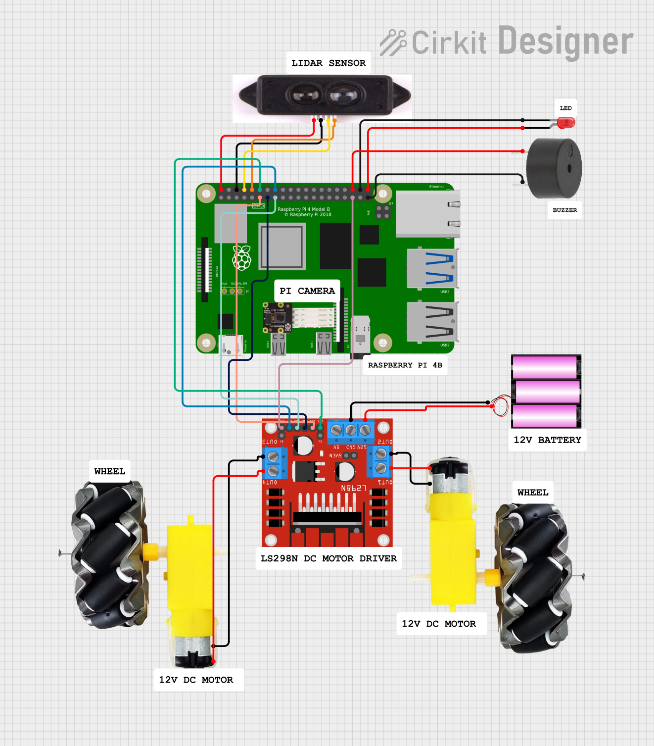
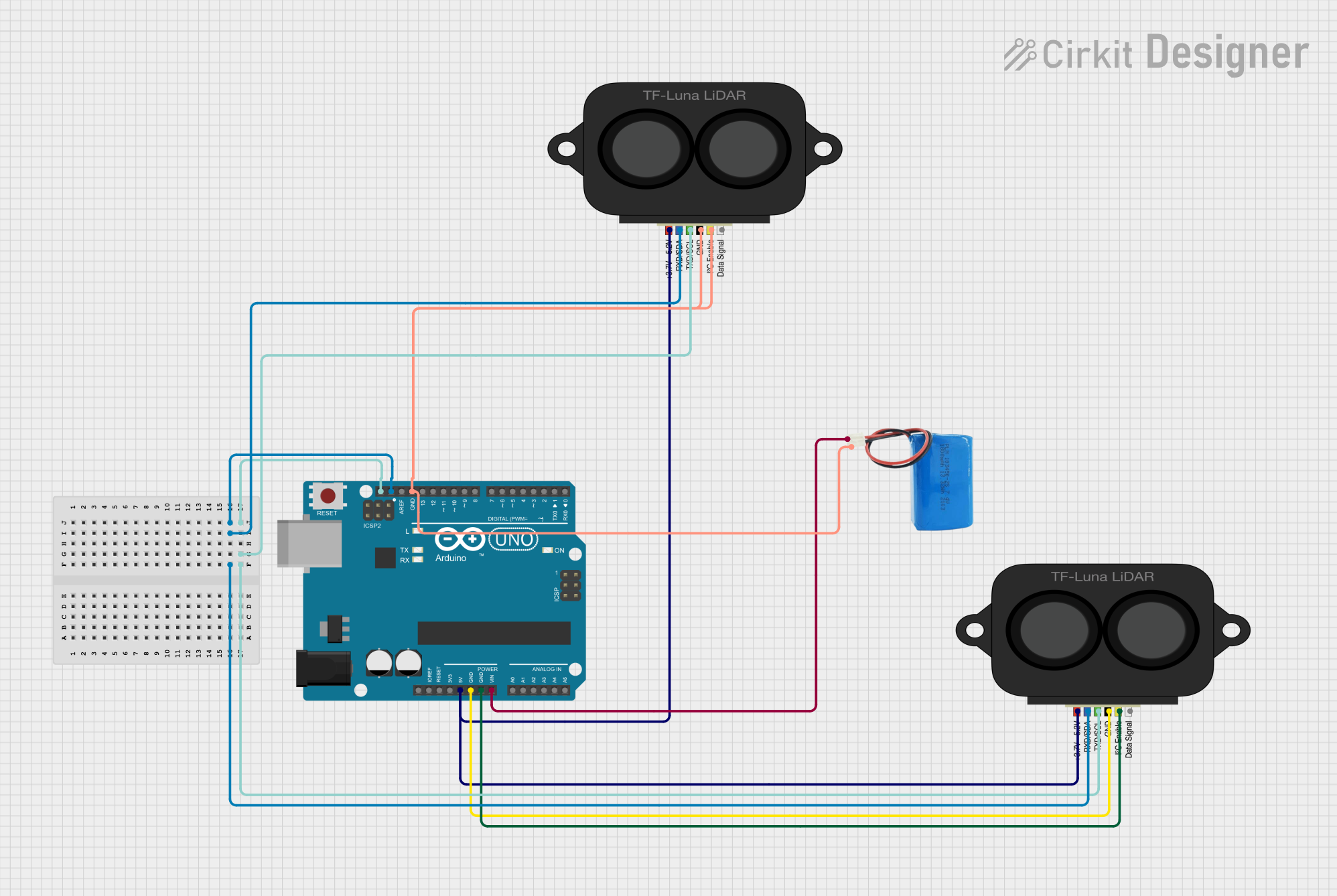
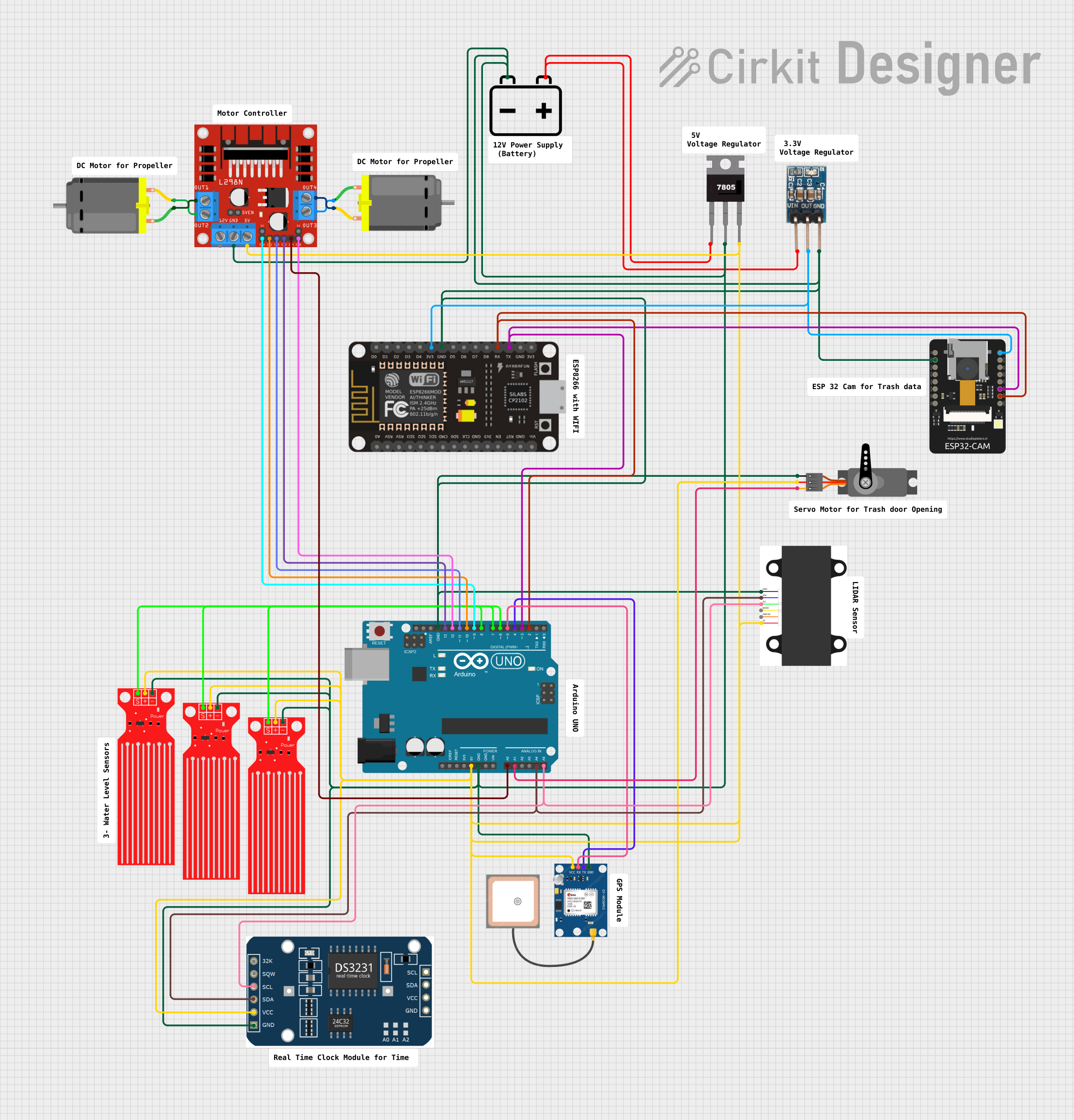

Explore Projects Built with lidar
Technical Specifications
Below are the general technical specifications for a typical Lidar module. Note that specific models may vary in their exact parameters.
| Parameter | Specification |
|---|---|
| Operating Voltage | 5V DC |
| Power Consumption | 1W to 5W (depending on the model) |
| Detection Range | 0.1m to 40m (short-range models) |
| Measurement Accuracy | ±2 cm |
| Field of View (FOV) | 360° (rotating Lidar) or 120° (fixed Lidar) |
| Laser Wavelength | 850 nm to 1550 nm (infrared) |
| Communication Interface | UART, I2C, or SPI |
| Operating Temperature | -10°C to 60°C |
| Dimensions | Varies by model (e.g., 50mm x 50mm x 70mm) |
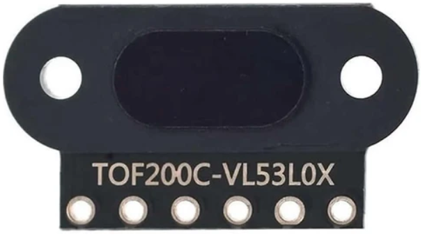
Pin Configuration
The pinout for a typical Lidar module is as follows:
| Pin | Name | Description |
|---|---|---|
| 1 | VCC | Power supply input (5V DC) |
| 2 | GND | Ground connection |
| 3 | TX | UART Transmit (data output) |
| 4 | RX | UART Receive (data input) |
| 5 | PWM/Trigger | Optional pin for triggering or PWM output (if available) |
Usage Instructions
How to Use the Lidar in a Circuit
- Power the Lidar Module: Connect the VCC pin to a 5V DC power source and the GND pin to ground.
- Connect Communication Pins: Use the TX and RX pins to interface with a microcontroller (e.g., Arduino UNO) via UART. Ensure proper voltage levels for communication.
- Optional Triggering: If the module supports a trigger or PWM pin, connect it to a GPIO pin on the microcontroller for additional control.
- Mounting: Secure the Lidar module on a stable platform to avoid vibrations that could affect measurements.
Important Considerations and Best Practices
- Avoid Direct Sunlight: Lidar performance can degrade in direct sunlight due to interference with the laser signal.
- Ensure Proper Alignment: For fixed Lidar modules, ensure the laser is aligned with the target area for accurate measurements.
- Use a Stable Power Source: Voltage fluctuations can affect the accuracy of the Lidar readings.
- Check Communication Settings: Configure the baud rate and communication protocol (e.g., UART) to match the Lidar module's specifications.
Example: Connecting Lidar to Arduino UNO
Below is an example of how to connect and use a Lidar module with an Arduino UNO via UART.
Circuit Connections
- Lidar VCC → Arduino 5V
- Lidar GND → Arduino GND
- Lidar TX → Arduino RX (Pin 0)
- Lidar RX → Arduino TX (Pin 1)
Arduino Code
#include <SoftwareSerial.h>

// Define RX and TX pins for SoftwareSerial
SoftwareSerial lidarSerial(10, 11); // RX = Pin 10, TX = Pin 11

void setup() {
  Serial.begin(9600); // Initialize Serial Monitor
  lidarSerial.begin(115200); // Initialize Lidar communication
  Serial.println("Lidar Module Initialized");
}

void loop() {
  if (lidarSerial.available()) {
    // Read data from Lidar and print to Serial Monitor
    String lidarData = "";
    while (lidarSerial.available()) {
      char c = lidarSerial.read();
      lidarData += c;
    }
    Serial.println("Lidar Data: " + lidarData);
  }
}
Notes:
- Replace
115200with the baud rate specified by your Lidar module. - Use SoftwareSerial if the Arduino's hardware UART (pins 0 and 1) is already in use.
Troubleshooting and FAQs
Common Issues
No Data Received from Lidar
- Solution: Check the TX and RX connections. Ensure the baud rate matches the Lidar module's specifications.
Inaccurate Distance Measurements
- Solution: Ensure the Lidar is not exposed to direct sunlight or reflective surfaces that could interfere with the laser.
Lidar Module Overheating
- Solution: Verify that the power supply voltage is within the specified range. Avoid prolonged operation in high-temperature environments.
Intermittent Communication
- Solution: Use shorter wires for UART communication to reduce noise. Add pull-up resistors if necessary.
FAQs
Q: Can Lidar detect transparent objects?
A: Lidar struggles with transparent or highly reflective objects, as the laser may pass through or scatter unpredictably.
Q: What is the maximum range of a Lidar module?
A: The range depends on the model, but typical short-range modules can detect objects up to 40 meters.
Q: Can I use Lidar outdoors?
A: Yes, but performance may be affected by environmental factors such as sunlight, rain, or fog. Use weatherproof Lidar modules for outdoor applications.
Q: How do I clean the Lidar lens?
A: Use a soft, lint-free cloth to gently clean the lens. Avoid using abrasive materials or liquids that could damage the surface.