Cirkit Designer Logo
Cirkit Designer
Your all-in-one circuit design IDE
Home / 
Component Documentation

How to Use Adafruit 7 Segment FeatherWing - Yellow: Examples, Pinouts, and Specs

Image of Adafruit 7 Segment FeatherWing - Yellow
Cirkit Designer LogoDesign with Adafruit 7 Segment FeatherWing - Yellow in Cirkit Designer

Introduction

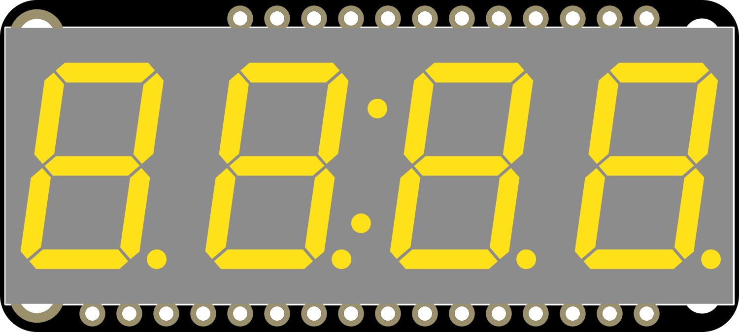
The Adafruit 7 Segment FeatherWing - Yellow is a compact, easy-to-use LED display module designed for displaying numerical data and simple alphanumeric characters. This module features a seven-segment LED display with bright yellow digits, making it highly visible even in well-lit conditions. It is commonly used in digital clocks, timers, counters, and other projects where numerical output is required.

Explore Projects Built with Adafruit 7 Segment FeatherWing - Yellow

Use Cirkit Designer to design, explore, and prototype these projects online. Some projects support real-time simulation. Click "Open Project" to start designing instantly!
Arduino UNO and OLED FeatherWing Display: Battery-Powered Hello World Project
Image of ARDUINO_SSD1306: A project utilizing Adafruit 7 Segment FeatherWing - Yellow in a practical application
This circuit consists of an Arduino UNO connected to an Adafruit OLED FeatherWing display via I2C communication (SDA and SCL lines). The Arduino is powered through a Vcc source and provides 3.3V and GND connections to the OLED display. The Arduino runs a program to display 'Hello, World!' on the OLED screen.
Cirkit Designer LogoOpen Project in Cirkit Designer
Arduino UNO Controlled Dual Seven Segment Display with Pushbutton Interaction and AHT10 Temperature Sensor
Image of enel290: A project utilizing Adafruit 7 Segment FeatherWing - Yellow in a practical application
This circuit features an Arduino UNO microcontroller connected to two seven-segment displays, a pushbutton, a red LED with a 330-ohm resistor, and an AHT10 temperature and humidity sensor. The Arduino controls the segments of the displays via its digital pins and reads the pushbutton state. The LED is used as an indicator, and the AHT10 sensor interfaces with the Arduino over I2C to provide environmental data.
Cirkit Designer LogoOpen Project in Cirkit Designer
ESP32-Based Vibration Feedback System with Quad Alphanumeric Display and ADXL343 Accelerometer
Image of EC444 - Quest 3: A project utilizing Adafruit 7 Segment FeatherWing - Yellow in a practical application
This circuit features an Adafruit HUZZAH32 ESP32 Feather board as the central microcontroller, which is connected to an Adafruit Quad AlphaNumeric Featherwing display and an Adafruit ADXL343 accelerometer via I2C communication (SCL and SDA lines). The ESP32 controls a vibration motor connected to one of its GPIO pins (A5_IO4) and shares a common power supply (3.3V) and ground (GND) with the other components. The purpose of this circuit is likely to read acceleration data, display information on the alphanumeric display, and provide haptic feedback through the vibration motor.
Cirkit Designer LogoOpen Project in Cirkit Designer
Arduino UNO Controlled NeoPixel Ring Light Show
Image of 6 Ring Series: A project utilizing Adafruit 7 Segment FeatherWing - Yellow in a practical application
This circuit consists of an Arduino UNO microcontroller connected to six Adafruit 12 NeoPixel Rings, each with 12 LEDs, for a total of 72 LEDs. The Arduino controls the LEDs to display a yellow color with varying brightness, creating a pulsating effect.
Cirkit Designer LogoOpen Project in Cirkit Designer

Explore Projects Built with Adafruit 7 Segment FeatherWing - Yellow

Use Cirkit Designer to design, explore, and prototype these projects online. Some projects support real-time simulation. Click "Open Project" to start designing instantly!
Image of ARDUINO_SSD1306: A project utilizing Adafruit 7 Segment FeatherWing - Yellow in a practical application
Arduino UNO and OLED FeatherWing Display: Battery-Powered Hello World Project
This circuit consists of an Arduino UNO connected to an Adafruit OLED FeatherWing display via I2C communication (SDA and SCL lines). The Arduino is powered through a Vcc source and provides 3.3V and GND connections to the OLED display. The Arduino runs a program to display 'Hello, World!' on the OLED screen.
Cirkit Designer LogoOpen Project in Cirkit Designer
Image of enel290: A project utilizing Adafruit 7 Segment FeatherWing - Yellow in a practical application
Arduino UNO Controlled Dual Seven Segment Display with Pushbutton Interaction and AHT10 Temperature Sensor
This circuit features an Arduino UNO microcontroller connected to two seven-segment displays, a pushbutton, a red LED with a 330-ohm resistor, and an AHT10 temperature and humidity sensor. The Arduino controls the segments of the displays via its digital pins and reads the pushbutton state. The LED is used as an indicator, and the AHT10 sensor interfaces with the Arduino over I2C to provide environmental data.
Cirkit Designer LogoOpen Project in Cirkit Designer
Image of EC444 - Quest 3: A project utilizing Adafruit 7 Segment FeatherWing - Yellow in a practical application
ESP32-Based Vibration Feedback System with Quad Alphanumeric Display and ADXL343 Accelerometer
This circuit features an Adafruit HUZZAH32 ESP32 Feather board as the central microcontroller, which is connected to an Adafruit Quad AlphaNumeric Featherwing display and an Adafruit ADXL343 accelerometer via I2C communication (SCL and SDA lines). The ESP32 controls a vibration motor connected to one of its GPIO pins (A5_IO4) and shares a common power supply (3.3V) and ground (GND) with the other components. The purpose of this circuit is likely to read acceleration data, display information on the alphanumeric display, and provide haptic feedback through the vibration motor.
Cirkit Designer LogoOpen Project in Cirkit Designer
Image of 6 Ring Series: A project utilizing Adafruit 7 Segment FeatherWing - Yellow in a practical application
Arduino UNO Controlled NeoPixel Ring Light Show
This circuit consists of an Arduino UNO microcontroller connected to six Adafruit 12 NeoPixel Rings, each with 12 LEDs, for a total of 72 LEDs. The Arduino controls the LEDs to display a yellow color with varying brightness, creating a pulsating effect.
Cirkit Designer LogoOpen Project in Cirkit Designer

Common Applications and Use Cases

  • Digital clocks and timers
  • Counters and scoreboards
  • Temperature displays
  • Simple calculators
  • User interfaces for various projects

Technical Specifications

Key Technical Details

  • Display Color: Yellow
  • Operating Voltage: 3.3V to 5V
  • Max Current Draw: 100mA per digit
  • Common Anode/Cathode: Common cathode
  • Interface: I2C
  • I2C Addresses: 0x70 (default), selectable with jumpers

Pin Configuration and Descriptions

Pin Description
GND Ground connection
VCC Power supply (3.3V to 5V)
SDA I2C data line
SCL I2C clock line
RST Reset pin (optional use)

Usage Instructions

How to Use the Component in a Circuit

  1. Powering the Display: Connect the VCC pin to a 3.3V or 5V power supply and the GND pin to the ground.
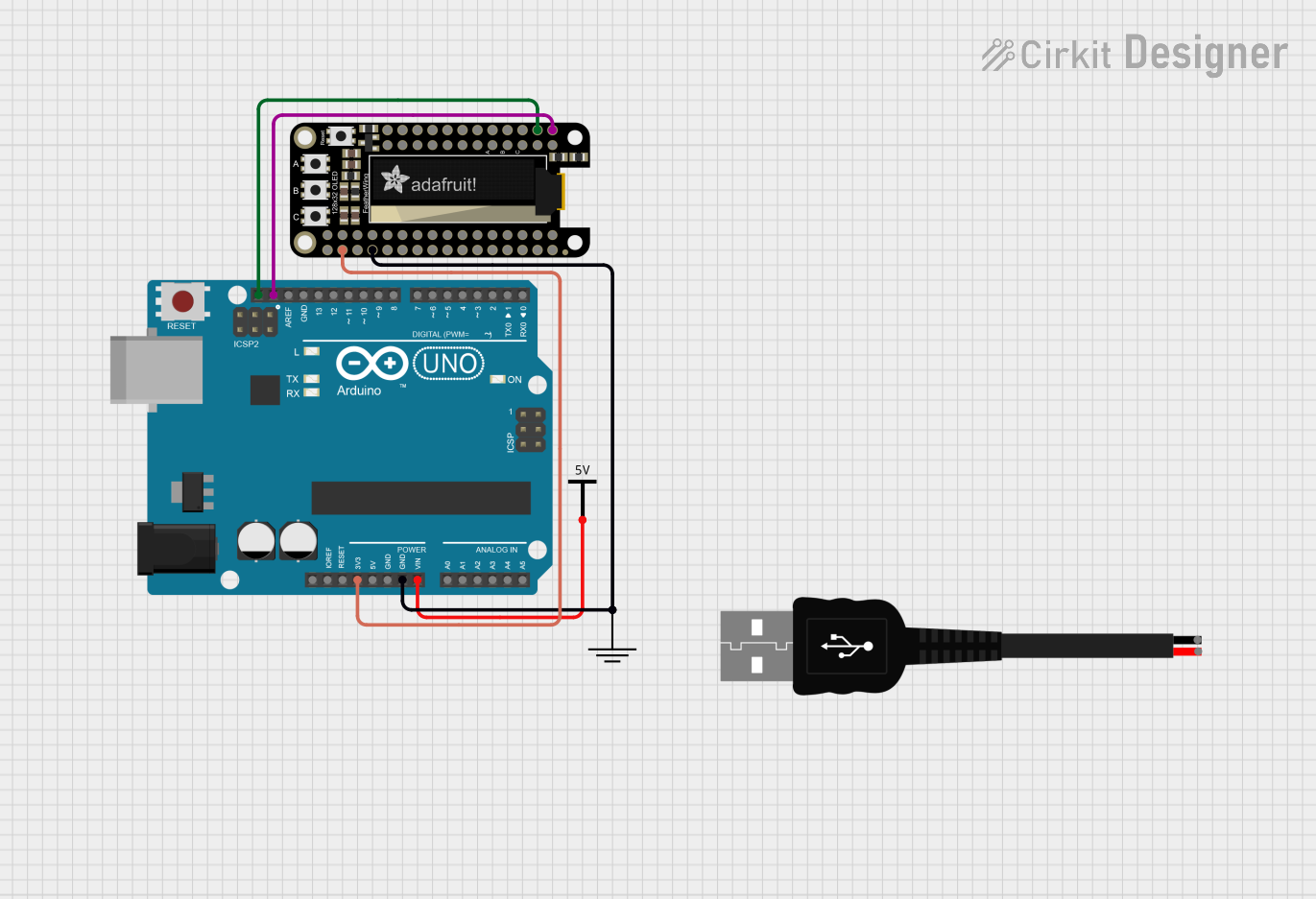
  2. I2C Communication: Connect the SDA and SCL pins to the corresponding I2C data and clock lines on your microcontroller (e.g., Arduino UNO).
  3. Address Selection: If using multiple displays, adjust the I2C address using the onboard jumpers.
  4. Programming: Use the Adafruit LED Backpack library to control the display via I2C.

Important Considerations and Best Practices

  • Ensure that the power supply voltage matches the operating voltage of the FeatherWing to prevent damage.
  • When daisy-chaining multiple displays, verify that the total current draw does not exceed the power supply's capacity.
  • Use pull-up resistors on the I2C lines if they are not already present on the microcontroller board.

Example Code for Arduino UNO

#include <Wire.h>
#include <Adafruit_GFX.h>
#include <Adafruit_LEDBackpack.h>

Adafruit_7segment matrix = Adafruit_7segment();

void setup() {
  matrix.begin(0x70); // Initialize the display with its I2C address
}

void loop() {
  matrix.print(1234); // Display the number 1234
  matrix.writeDisplay(); // Refresh the display with new data
  delay(500); // Wait for half a second
}

Troubleshooting and FAQs

Common Issues

  • Display Not Lighting Up: Check the power connections and ensure the I2C lines are correctly connected.
  • Garbled or Incorrect Output: Verify that the I2C address is set correctly and that there are no conflicts on the I2C bus.
  • Dim Display: Ensure that the power supply can deliver sufficient current for the display.

Solutions and Tips for Troubleshooting

  • Double-check wiring connections for any loose or incorrect connections.
  • Use a multimeter to verify that the correct voltage is reaching the display.
  • Check for solder bridges or shorts on the display module.
  • Review your code to ensure that the correct library and functions are being used.

FAQs

Q: Can I use this display with a 3.3V system? A: Yes, the display can operate at 3.3V, but ensure that the I2C logic levels are compatible.

Q: How do I change the I2C address? A: Adjust the address by changing the position of the jumpers on the back of the display module.

Q: Can I display letters as well as numbers? A: The display can show some basic alphanumeric characters (e.g., A, b, C, d, E, F).

Q: How many of these displays can I chain together? A: You can chain up to 8 displays by setting unique I2C addresses for each using the onboard jumpers.