How to Use P300: Examples, Pinouts, and Specs
Introduction
The P300 is a programmable power supply designed to provide adjustable voltage and current outputs. It is widely used in testing, prototyping, and powering electronic circuits. With its precision control and reliability, the P300 is an essential tool for engineers, hobbyists, and researchers working on a variety of electronic projects.
Explore Projects Built with P300


Explore Projects Built with P300
Common Applications and Use Cases
- Powering and testing electronic circuits during development
- Simulating different voltage and current conditions for device testing
- Battery charging and discharging experiments
- Educational purposes in electronics labs
- Industrial applications requiring precise power delivery
Technical Specifications
The P300 is designed to deliver stable and adjustable power with the following specifications:
| Parameter | Value |
|---|---|
| Manufacturer | P300 |
| Manufacturer Part ID | P300 |
| Input Voltage | 100-240V AC, 50/60Hz |
| Output Voltage Range | 0-30V DC |
| Output Current Range | 0-5A DC |
| Voltage Resolution | 10mV |
| Current Resolution | 1mA |
| Display Type | Digital (LCD/LED) |
| Communication Interface | USB, RS232 (optional) |
| Protection Features | Overvoltage, Overcurrent, Overheat |
| Dimensions | 200mm x 150mm x 80mm |
| Weight | 1.5kg |
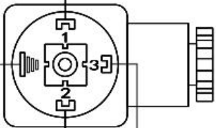
Pin Configuration and Descriptions
The P300 power supply has the following input and output terminals:
| Pin/Terminal | Description |
|---|---|
| AC Input | Connects to the mains power supply (100-240V AC). |
| Positive Output (+) | Provides the positive DC voltage output. |
| Negative Output (-) | Provides the negative DC voltage output (ground). |
| USB Port | For communication with a PC or microcontroller. |
| RS232 Port | Optional interface for serial communication. |
Usage Instructions
How to Use the P300 in a Circuit
- Connect the Power Supply: Plug the P300 into a mains power outlet using the provided AC cable.
- Set Voltage and Current:
- Use the control knobs or buttons to adjust the desired voltage and current.
- The digital display will show the set values in real-time.
- Connect to the Circuit:
- Attach the positive output terminal (+) to the positive input of your circuit.
- Attach the negative output terminal (-) to the ground of your circuit.
- Enable Output: Turn on the output using the "Output On/Off" button. The P300 will now supply power to your circuit.
- Monitor the Output: Continuously monitor the voltage and current on the display to ensure proper operation.
Important Considerations and Best Practices
- Set Limits: Always set the current limit to protect your circuit from overcurrent damage.
- Check Connections: Double-check all connections before enabling the output to avoid short circuits.
- Use Proper Cables: Use cables rated for the required current to prevent overheating.
- Ventilation: Ensure adequate ventilation around the P300 to prevent overheating.
- Communication: If using the USB or RS232 interface, install the necessary drivers and software provided by the manufacturer.
Example: Controlling the P300 with an Arduino UNO
The P300 can be controlled via its USB interface using serial communication. Below is an example Arduino sketch to set the voltage and current:
#include <SoftwareSerial.h>

// Define RX and TX pins for communication with the P300
SoftwareSerial p300Serial(10, 11); // RX = pin 10, TX = pin 11

void setup() {
  Serial.begin(9600); // Initialize serial monitor
  p300Serial.begin(9600); // Initialize communication with P300

  // Set voltage to 12V
  p300Serial.println("VSET 12.0");
  delay(100); // Wait for the command to process

  // Set current to 2A
  p300Serial.println("ISET 2.0");
  delay(100); // Wait for the command to process

  // Enable output
  p300Serial.println("OUT 1");
  delay(100); // Wait for the command to process

  Serial.println("P300 configured and output enabled.");
}

void loop() {
  // Continuously monitor the P300 status (optional)
  if (p300Serial.available()) {
    String response = p300Serial.readString();
    Serial.println("P300 Response: " + response);
  }
}
Note: Replace "VSET", "ISET", and "OUT" commands with the actual command set provided in the P300 communication protocol documentation.
Troubleshooting and FAQs
Common Issues and Solutions
No Output Voltage
- Cause: Output is disabled.
- Solution: Press the "Output On/Off" button or send the appropriate command via USB/RS232.
Overcurrent Protection Triggered
- Cause: The connected circuit is drawing more current than the set limit.
- Solution: Increase the current limit or check the circuit for faults.
Overheating
- Cause: Insufficient ventilation or prolonged high-power operation.
- Solution: Ensure proper ventilation and avoid operating at maximum power for extended periods.
Communication Failure
- Cause: Incorrect USB/RS232 settings or missing drivers.
- Solution: Verify the communication settings (baud rate, parity, etc.) and install the required drivers.
FAQs
Q: Can the P300 be used to charge batteries?
- A: Yes, but ensure the voltage and current are set according to the battery specifications.
Q: What happens if the input voltage exceeds 240V AC?
- A: The P300 is designed to handle up to 240V AC. Exceeding this limit may damage the device.
Q: Is the P300 compatible with microcontrollers other than Arduino?
- A: Yes, the P300 can be controlled by any microcontroller that supports serial communication.
Q: How do I reset the P300 to factory settings?
- A: Refer to the user manual for the specific reset procedure, typically involving a combination of button presses.
This concludes the documentation for the P300 programmable power supply. For further assistance, refer to the manufacturer's user manual or contact technical support.