How to Use AS5147: Examples, Pinouts, and Specs
Introduction
The AS5147, manufactured by AMS, is a high-resolution magnetic rotary position sensor designed for precise angular position measurements. It employs contactless Hall effect technology to detect the position of a magnet placed above the sensor. With a 14-bit resolution and digital output, the AS5147 is ideal for applications requiring high accuracy and reliability.
Explore Projects Built with AS5147


Explore Projects Built with AS5147
Common Applications
- Robotics: Joint position sensing and motor control
- Automotive: Steering angle detection and throttle position sensing
- Industrial Automation: Rotary encoders and motor feedback systems
- Consumer Electronics: Joystick and knob position sensing
Technical Specifications
The AS5147 offers robust performance and flexibility for a wide range of applications. Below are its key technical details:
Key Specifications
| Parameter | Value |
|---|---|
| Supply Voltage (VDD) | 3.3V or 5V |
| Resolution | 14-bit (16,384 positions per revolution) |
| Interface | SPI, PWM, ABI (Incremental) |
| Maximum Speed | 28,000 RPM |
| Operating Temperature | -40°C to +150°C |
| Magnetic Field Strength | 30 - 70 mT |
| Power Consumption | 18 mA (typical) |
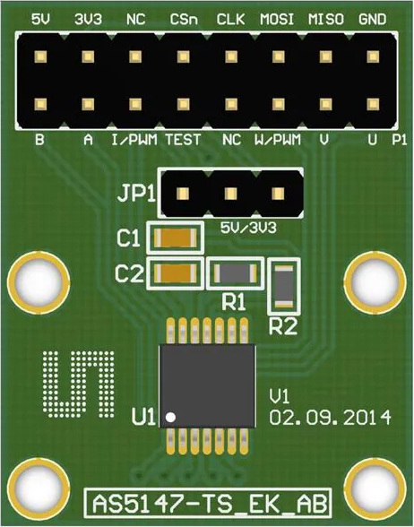
Pin Configuration and Descriptions
The AS5147 is typically available in a TSSOP-14 package. Below is the pinout and description:
| Pin Number | Pin Name | Description |
|---|---|---|
| 1 | VDD3V3 | 3.3V Power Supply |
| 2 | VDD5V | 5V Power Supply |
| 3 | GND | Ground |
| 4 | CSn | Chip Select (Active Low) for SPI Communication |
| 5 | CLK | SPI Clock Input |
| 6 | DO | SPI Data Output |
| 7 | DI | SPI Data Input |
| 8 | PWM | Pulse Width Modulation Output |
| 9 | A | Incremental Encoder Output (Channel A) |
| 10 | B | Incremental Encoder Output (Channel B) |
| 11 | Index | Incremental Encoder Index Pulse |
| 12 | PROG | Programming Pin (for OTP configuration) |
| 13 | TEST | Test Pin (leave unconnected in normal operation) |
| 14 | NC | Not Connected |
Usage Instructions
The AS5147 is straightforward to integrate into a circuit. Below are the steps and best practices for using the sensor:
Circuit Connection
- Power Supply: Connect the VDD3V3 or VDD5V pin to a 3.3V or 5V power source, respectively, and GND to ground.
- SPI Communication: Connect the CSn, CLK, DO, and DI pins to the corresponding SPI pins on your microcontroller.
- Magnet Placement: Place a diametrically magnetized magnet above the sensor, ensuring it is centered and within the recommended distance (1-3 mm).
- Output Options: Use the SPI interface for digital data, or connect the PWM, A, B, and Index pins for alternative output modes.
Arduino UNO Example Code
The AS5147 can be interfaced with an Arduino UNO using the SPI protocol. Below is an example code snippet:
#include <SPI.h>

// Define SPI pins for AS5147
const int CS_PIN = 10; // Chip Select pin

void setup() {
  Serial.begin(9600); // Initialize serial communication
  SPI.begin();        // Initialize SPI
  pinMode(CS_PIN, OUTPUT);
  digitalWrite(CS_PIN, HIGH); // Set CS pin to HIGH (inactive)
}

uint16_t readAS5147() {
  uint16_t angle = 0;

  digitalWrite(CS_PIN, LOW); // Activate the sensor
  delayMicroseconds(1);      // Small delay for stability

  // Send command to read angle (16-bit data)
  uint16_t command = 0xFFFF; // Example command for angle read
  angle = SPI.transfer16(command);

  digitalWrite(CS_PIN, HIGH); // Deactivate the sensor
  return angle;
}

void loop() {
  uint16_t angle = readAS5147(); // Read angle from AS5147
  Serial.print("Angle: ");
  Serial.println(angle);        // Print angle to serial monitor
  delay(100);                   // Delay for readability
}
Best Practices
- Ensure the magnet is properly aligned and within the specified distance for accurate readings.
- Use decoupling capacitors (e.g., 100 nF) near the power supply pins to reduce noise.
- Avoid placing the sensor near strong external magnetic fields that could interfere with measurements.
Troubleshooting and FAQs
Common Issues and Solutions
No Output or Incorrect Readings:
- Verify the power supply voltage and connections.
- Ensure the magnet is properly aligned and within the recommended distance.
- Check SPI connections and ensure the correct pin configuration.
Noise in Output:
- Add decoupling capacitors near the power supply pins.
- Use shielded cables for SPI communication to reduce electromagnetic interference.
Sensor Not Responding to SPI Commands:
- Confirm the SPI clock speed is within the sensor's specifications.
- Ensure the CSn pin is toggled correctly during communication.
FAQs
Q: Can the AS5147 be used with a 5V microcontroller?
A: Yes, the AS5147 supports both 3.3V and 5V power supplies, making it compatible with 5V microcontrollers like the Arduino UNO.
Q: What type of magnet should I use with the AS5147?
A: Use a diametrically magnetized magnet with a magnetic field strength of 30-70 mT.
Q: How do I switch between SPI and PWM output modes?
A: The output mode is configured via the sensor's internal registers. Refer to the AS5147 datasheet for detailed instructions on register configuration.
Q: What is the maximum distance between the magnet and the sensor?
A: The recommended distance is 1-3 mm for optimal performance.