How to Use SparkFun_ACS723_Current_Sensor_Breakout: Examples, Pinouts, and Specs
Introduction
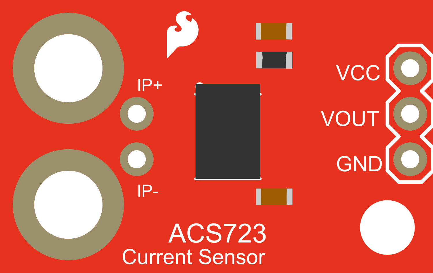
The SparkFun ACS723 Current Sensor Breakout is a versatile and robust module designed for measuring AC or DC currents. Utilizing the Allegro ACS723 Hall effect current sensor, it provides an analog voltage output that is proportional to the current passing through the sensor. This breakout is ideal for applications such as power supply monitoring, battery chargers, and current monitoring in various electronic projects.
Explore Projects Built with SparkFun_ACS723_Current_Sensor_Breakout

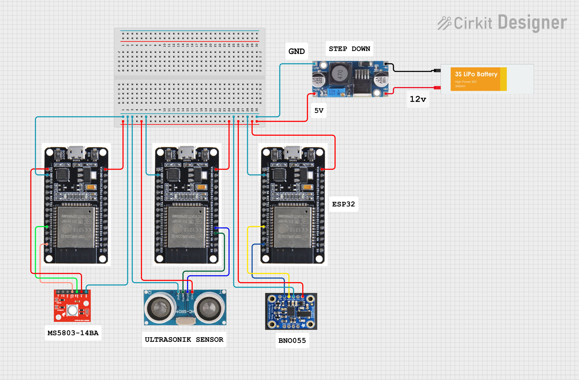

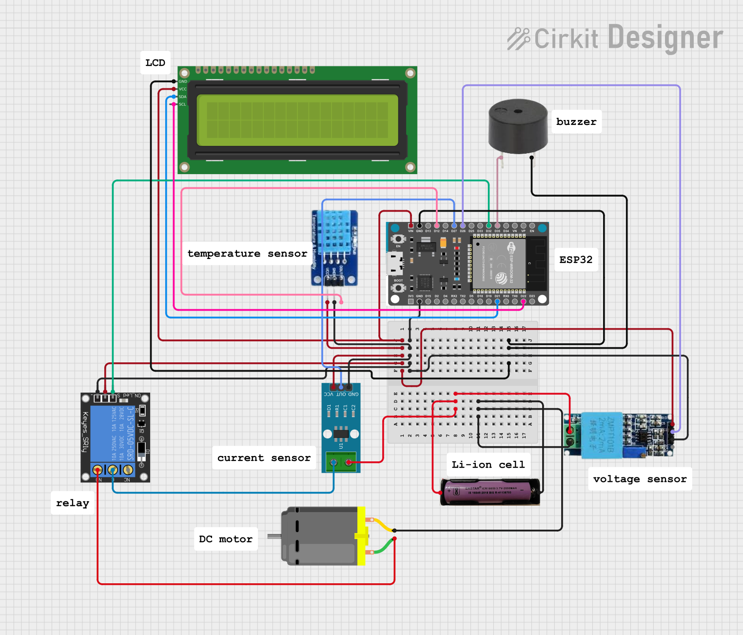
Explore Projects Built with SparkFun_ACS723_Current_Sensor_Breakout
Common Applications and Use Cases
- Over-current protection circuits
- Battery chargers and management systems
- Power supply monitoring
- Energy metering
- Motor control feedback
Technical Specifications
Key Technical Details
- Supply Voltage (VCC): 4.5V to 5.5V
- Sensing Current Range: +/-31A
- Output Sensitivity: 400 mV/A
- Bandwidth: 80 kHz
- Isolation Voltage: 2.4 kV
- Operating Temperature: -40°C to 150°C
Pin Configuration and Descriptions
| Pin Number | Name | Description |
|---|---|---|
| 1 | VCC | Supply voltage for the sensor (4.5V to 5.5V) |
| 2 | GND | Ground reference for the sensor |
| 3 | OUT | Analog voltage output proportional to the current |
| 4 | FLTR | Output filter pin, can be left unconnected for default filter settings |
| 5 | IP+ | Current input, connect to the positive side of the current path |
| 6 | IP- | Current input, connect to the negative side of the current path |
Usage Instructions
How to Use the Component in a Circuit
Powering the Sensor: Connect the VCC pin to a 4.5V to 5.5V power supply and the GND pin to the common ground.
Current Sensing: Place the sensor in series with the load such that the current you wish to measure flows through IP+ to IP-.
Reading the Output: Connect the OUT pin to an analog input on your microcontroller to read the voltage proportional to the current.
Important Considerations and Best Practices
- Ensure that the current does not exceed the maximum rating of +/-31A to prevent damage to the sensor.
- Avoid placing the sensor near strong magnetic fields that could interfere with the Hall effect measurement.
- Use twisted pair wires for IP+ and IP- to minimize the effect of external noise on the current measurement.
- If higher resolution is needed, consider using an operational amplifier to amplify the sensor output before reading it with a microcontroller.
Example Code for Arduino UNO
// SparkFun ACS723 Current Sensor Example for Arduino UNO

const int analogInPin = A0; // Analog input pin connected to OUT

void setup() {
  Serial.begin(9600); // Initialize serial communication at 9600 bits per second
}

void loop() {
  int sensorValue = analogRead(analogInPin); // Read the sensor output
  float voltage = sensorValue * (5.0 / 1023.0); // Convert to voltage
  float current = voltage / 0.4; // Convert voltage to current (sensitivity is 400mV/A)

  // Print the current reading to the Serial Monitor
  Serial.print("Current: ");
  Serial.print(current);
  Serial.println(" A");

  delay(1000); // Wait for a second before taking another reading
}
Troubleshooting and FAQs
Common Issues
- Inaccurate Readings: Ensure that the sensor is properly calibrated and that there are no strong magnetic fields interfering with the sensor.
- No Output Voltage: Check the connections to ensure that the sensor is powered and that the current path is correctly set up through IP+ and IP-.
Solutions and Tips for Troubleshooting
- If the output seems noisy, consider adding a capacitor between the FLTR pin and ground to adjust the filter settings.
- For more stable readings, average multiple sensor readings.
- Ensure that the power supply is stable and within the specified voltage range.
FAQs
Q: Can I measure current in both directions? A: Yes, the ACS723 can measure both positive and negative currents up to +/-31A.
Q: What is the resolution of the sensor? A: The resolution depends on the analog-to-digital converter (ADC) of the microcontroller. For a 10-bit ADC like on the Arduino UNO, the resolution is approximately 4.9 mA per bit (5V/1023 steps/0.4 V/A).
Q: Is the sensor isolated from the high current path? A: Yes, the sensor provides galvanic isolation up to 2.4 kV between the current path and the sensor outputs.