How to Use LED Matrix 8x16 DOT: Examples, Pinouts, and Specs
Introduction
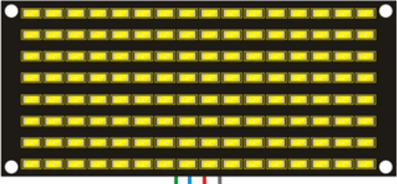
The Keyestudio KS0357 8x16 LED Matrix Panel is a versatile display module consisting of 128 individual LEDs arranged in 8 rows and 16 columns. This component is ideal for creating dynamic visual displays, such as scrolling text, simple graphics, and animations. Its compact design and ease of use make it a popular choice for hobbyists, students, and professionals working on electronic projects.
Explore Projects Built with LED Matrix 8x16 DOT

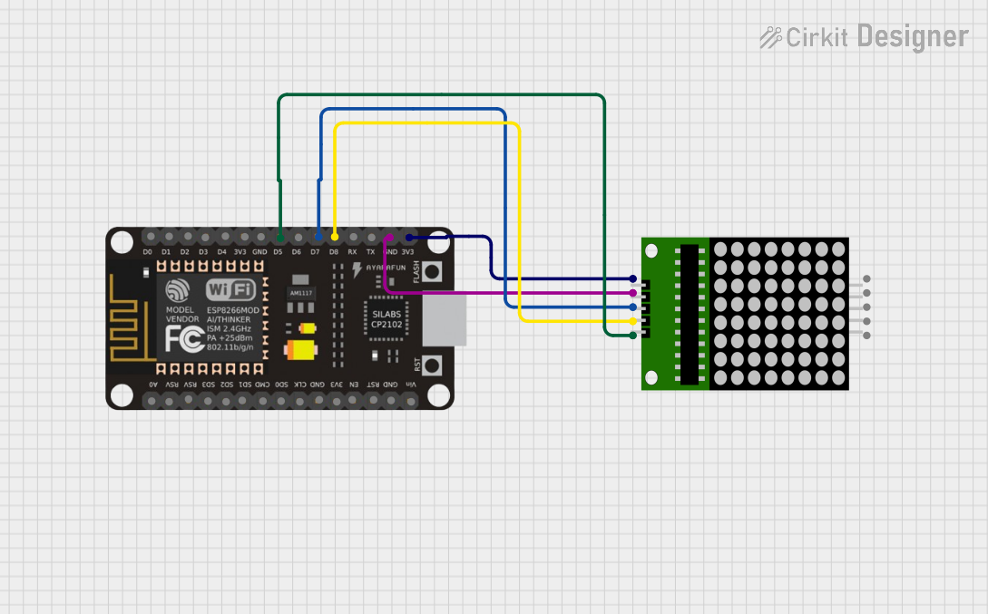

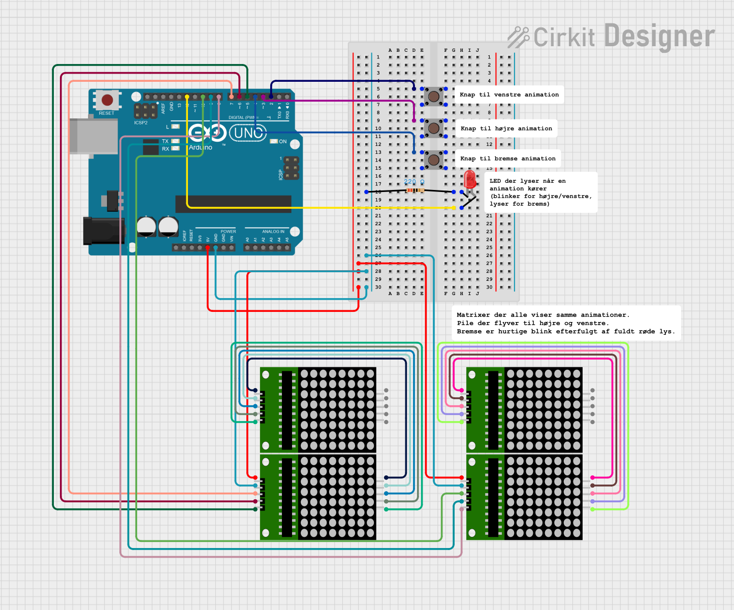
Explore Projects Built with LED Matrix 8x16 DOT
Common Applications and Use Cases
- Scrolling text displays
- Digital clocks and counters
- Simple animations and graphics
- Status indicators for IoT devices
- Educational projects and prototyping
Technical Specifications
The following table outlines the key technical details of the KS0357 8x16 LED Matrix Panel:
| Parameter | Specification |
|---|---|
| Manufacturer | Keyestudio |
| Part ID | KS0357 |
| LED Configuration | 8 rows × 16 columns (128 LEDs total) |
| Operating Voltage | 5V DC |
| Operating Current | ≤ 200mA |
| Communication Protocol | Serial (SPI-like interface) |
| Dimensions | 32mm × 64mm |
| LED Color | Red |
Pin Configuration and Descriptions
The KS0357 8x16 LED Matrix Panel has a 5-pin interface for connecting to a microcontroller. The pinout is as follows:
| Pin | Name | Description |
|---|---|---|
| 1 | VCC | Power supply input (5V DC). Connect to the 5V pin of the microcontroller. |
| 2 | GND | Ground. Connect to the GND pin of the microcontroller. |
| 3 | DIN | Data input. Used to send serial data to the LED matrix. |
| 4 | CS | Chip select. Used to enable or disable communication with the LED matrix. |
| 5 | CLK | Clock input. Synchronizes data transfer between the microcontroller and matrix. |
Usage Instructions
How to Use the Component in a Circuit
- Power the Matrix: Connect the
VCCpin to a 5V power source and theGNDpin to ground. - Connect Data Lines: Use the
DIN,CS, andCLKpins to interface with a microcontroller. These pins are typically connected to the SPI-compatible pins of the microcontroller. - Install Required Libraries: If using an Arduino, install the
LedControllibrary, which simplifies communication with the LED matrix. - Write Code: Use the library functions to control the LEDs, display text, or create animations.
Important Considerations and Best Practices
- Power Supply: Ensure the power supply can provide sufficient current (up to 200mA) to avoid dimming or flickering.
- Heat Management: Prolonged use at high brightness may generate heat. Ensure proper ventilation.
- Data Line Length: Keep the data lines as short as possible to minimize signal degradation.
- Daisy-Chaining: Multiple LED matrices can be connected in series for larger displays. Ensure proper addressing in the code.
Example Code for Arduino UNO
Below is an example of how to display scrolling text on the KS0357 8x16 LED Matrix Panel using the Arduino UNO:
#include <LedControl.h> // Include the LedControl library

// Initialize the LED matrix (DIN=12, CLK=11, CS=10, 1 device)
LedControl lc = LedControl(12, 11, 10, 1);

void setup() {
  // Wake up the LED matrix
  lc.shutdown(0, false); // Turn on the display
  lc.setIntensity(0, 8); // Set brightness level (0-15)
  lc.clearDisplay(0);    // Clear the display
}

void loop() {
  // Display scrolling text
  scrollText("HELLO WORLD");
}

void scrollText(String text) {
  int textLength = text.length();
  for (int i = 0; i < textLength * 8; i++) {
    lc.clearDisplay(0); // Clear the display before each frame
    for (int j = 0; j < textLength; j++) {
      // Display each character in the string
      lc.setChar(0, 7 - (i / 8) + j, text[j], false);
    }
    delay(100); // Adjust delay for scrolling speed
  }
}
Notes on the Code
- The
LedControllibrary simplifies communication with the LED matrix. - Adjust the
setIntensityfunction to control brightness. - Modify the
scrollTextfunction to display custom messages.
Troubleshooting and FAQs
Common Issues and Solutions
LEDs Not Lighting Up
- Cause: Incorrect wiring or insufficient power supply.
- Solution: Double-check all connections and ensure the power supply provides 5V and sufficient current.
Flickering or Dim LEDs
- Cause: Voltage drop or excessive current draw.
- Solution: Use a stable power source and ensure proper grounding.
No Response from the Matrix
- Cause: Incorrect pin connections or faulty code.
- Solution: Verify the
DIN,CS, andCLKconnections. Check the code for errors.
Scrolling Text Appears Garbled
- Cause: Timing issues or incorrect character mapping.
- Solution: Adjust the delay in the code and ensure the correct library is used.
FAQs
Q: Can I connect multiple KS0357 panels together?
A: Yes, the panels support daisy-chaining. Connect the DOUT pin of one panel to the DIN pin of the next, and configure the code to address multiple devices.
Q: What is the maximum brightness level?
A: The brightness can be set from 0 (minimum) to 15 (maximum) using the setIntensity function in the LedControl library.
Q: Can I use this matrix with a Raspberry Pi?
A: Yes, the matrix can be controlled using the SPI interface of a Raspberry Pi. However, you may need to use a different library, such as luma.led_matrix.
Q: Is the matrix compatible with 3.3V microcontrollers?
A: The matrix requires 5V for operation. Use a level shifter to safely interface with 3.3V microcontrollers.
By following this documentation, you can effectively integrate the Keyestudio KS0357 8x16 LED Matrix Panel into your projects and create stunning visual displays.