Cirkit Designer Logo
Cirkit Designer
Your all-in-one circuit design IDE
Home / 
Component Documentation

How to Use Adafruit MCP2221A USB to GPIO / ADC / DAC breakout: Examples, Pinouts, and Specs
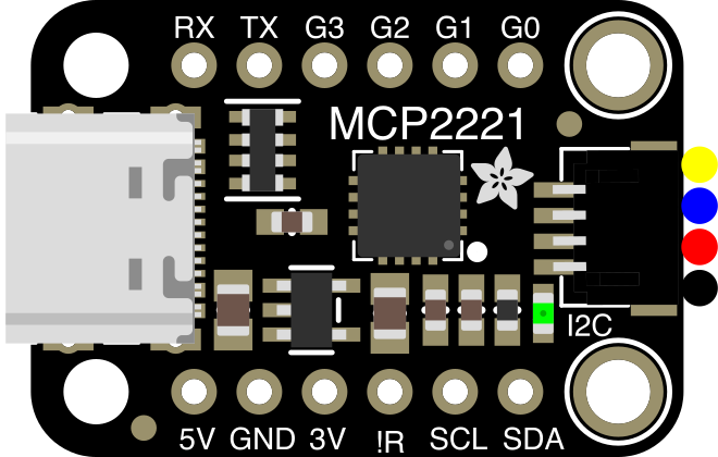

Image of Adafruit MCP2221A USB to GPIO / ADC / DAC breakout
Cirkit Designer LogoDesign with Adafruit MCP2221A USB to GPIO / ADC / DAC breakout in Cirkit Designer

Introduction

The Adafruit MCP2221A USB to GPIO / ADC / DAC breakout (Part ID: 4471) is a versatile and user-friendly board designed to bridge USB connectivity with GPIO, ADC, and DAC functionalities. This breakout board is based on the Microchip MCP2221A chip, which enables seamless communication between a computer and external devices via USB. It is ideal for prototyping, testing, and interfacing with sensors, actuators, and other peripherals.

Explore Projects Built with Adafruit MCP2221A USB to GPIO / ADC / DAC breakout
Use Cirkit Designer to design, explore, and prototype these projects online. Some projects support real-time simulation. Click "Open Project" to start designing instantly!
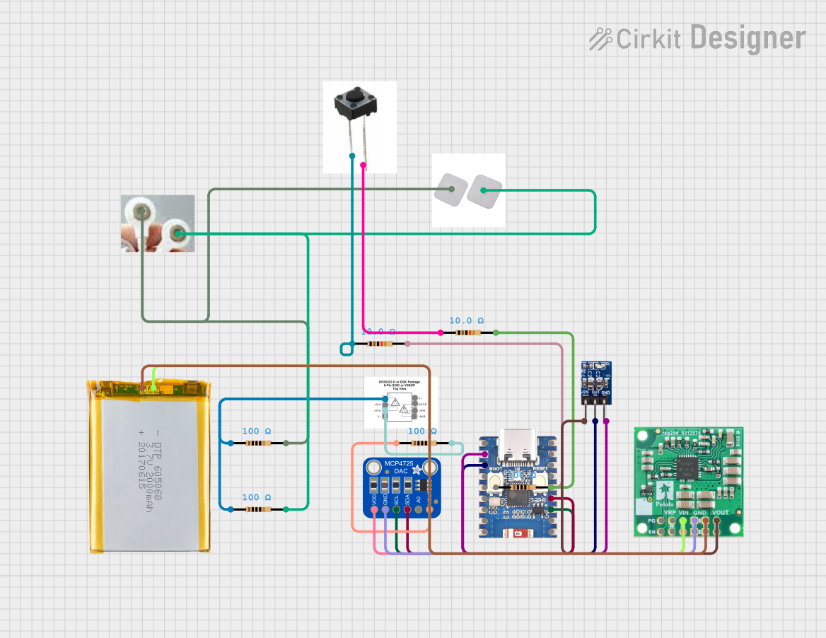
ESP32-C3 Mini and MCP4725 DAC Controlled Analog Output Circuit
Image of pp: A project utilizing Adafruit MCP2221A USB to GPIO / ADC / DAC breakout in a practical application
This circuit features an ESP32-C3 Mini microcontroller that interfaces with an Adafruit MCP4725 DAC via I2C for analog output, which is then fed into an OPA2333 operational amplifier. Power management is handled by a 5V step-down voltage regulator that receives power from a 2000mAh battery and supplies the ESP32-C3 and a 3.3V AMS1117 voltage regulator. Additionally, the circuit includes user input through buttons and electro pads, with debouncing provided by resistors.
Cirkit Designer LogoOpen Project in Cirkit Designer
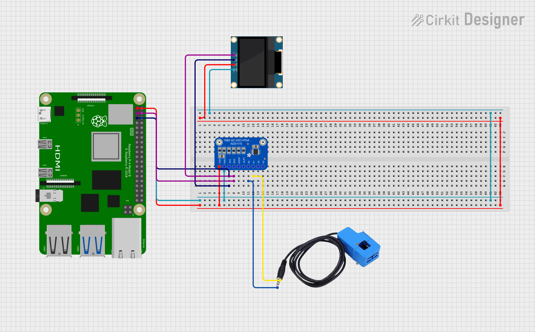
Raspberry Pi 4B with I2C Current Sensing and OLED Display
Image of iot task 2: A project utilizing Adafruit MCP2221A USB to GPIO / ADC / DAC breakout in a practical application
This circuit features a Raspberry Pi 4B as the central processing unit, interfaced with an Adafruit ADS1115 16-bit I2C ADC for analog-to-digital conversion and a 0.96" OLED display for visual output. The ADC is connected to a current sensor for measuring electrical current, with the sensor's output connected to the ADC's AIN0 pin and the burden resistor connected to AIN1. The Raspberry Pi communicates with both the ADC and the OLED display over the I2C bus, using GPIO2 (SDA) and GPIO3 (SCL) for data exchange.
Cirkit Designer LogoOpen Project in Cirkit Designer
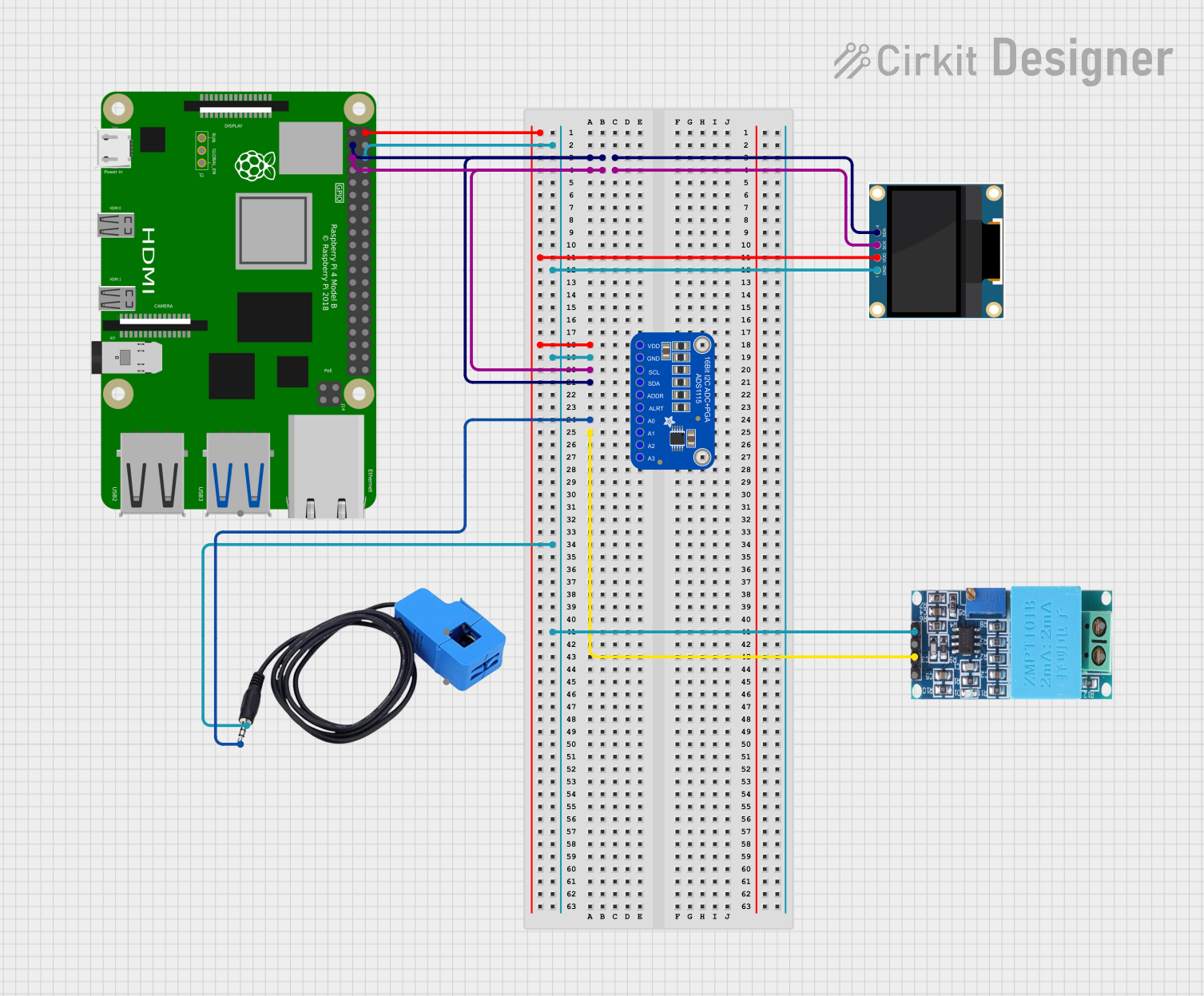
Raspberry Pi 4B with I2C Sensor Data Acquisition and OLED Display
Image of Task02: A project utilizing Adafruit MCP2221A USB to GPIO / ADC / DAC breakout in a practical application
This circuit features a Raspberry Pi 4B as the central processing unit, interfaced with an Adafruit ADS1115 16-bit ADC for analog-to-digital conversion, a current sensor, and a ZMPT101B voltage sensor for electrical parameter measurement. The Raspberry Pi communicates with the ADC and a 0.96" OLED display via I2C (using GPIO2 and GPIO3 for SDA and SCL lines, respectively), allowing for the monitoring and display of current and voltage readings. The ADC is connected to the current sensor and voltage sensor to digitize the analog signals for processing by the Raspberry Pi.
Cirkit Designer LogoOpen Project in Cirkit Designer
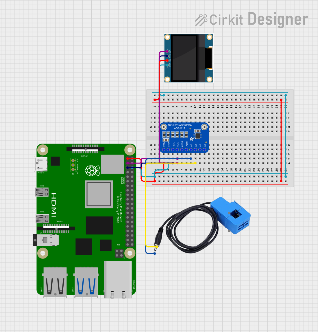
Raspberry Pi 4B-Based Current Monitoring System with I2C OLED Display
Image of Virtual Energy Monitoring Circuit: A project utilizing Adafruit MCP2221A USB to GPIO / ADC / DAC breakout in a practical application
This circuit features a Raspberry Pi 4B as the central processing unit, interfaced with an Adafruit ADS1115 16-bit I2C ADC for analog-to-digital conversion and a 0.96" OLED display for visual output. The ADS1115 is connected to a current sensor for measuring electrical current, with the sensor's output and burden pins connected to the ADC's analog input channels. The Raspberry Pi communicates with both the ADC and the OLED display over the I2C bus, using its GPIO2 and GPIO3 pins for data (SDA) and clock (SCL) lines, respectively.
Cirkit Designer LogoOpen Project in Cirkit Designer

Explore Projects Built with Adafruit MCP2221A USB to GPIO / ADC / DAC breakout

Use Cirkit Designer to design, explore, and prototype these projects online. Some projects support real-time simulation. Click "Open Project" to start designing instantly!
Image of pp: A project utilizing Adafruit MCP2221A USB to GPIO / ADC / DAC breakout in a practical application
ESP32-C3 Mini and MCP4725 DAC Controlled Analog Output Circuit
This circuit features an ESP32-C3 Mini microcontroller that interfaces with an Adafruit MCP4725 DAC via I2C for analog output, which is then fed into an OPA2333 operational amplifier. Power management is handled by a 5V step-down voltage regulator that receives power from a 2000mAh battery and supplies the ESP32-C3 and a 3.3V AMS1117 voltage regulator. Additionally, the circuit includes user input through buttons and electro pads, with debouncing provided by resistors.
Cirkit Designer LogoOpen Project in Cirkit Designer
Image of iot task 2: A project utilizing Adafruit MCP2221A USB to GPIO / ADC / DAC breakout in a practical application
Raspberry Pi 4B with I2C Current Sensing and OLED Display
This circuit features a Raspberry Pi 4B as the central processing unit, interfaced with an Adafruit ADS1115 16-bit I2C ADC for analog-to-digital conversion and a 0.96" OLED display for visual output. The ADC is connected to a current sensor for measuring electrical current, with the sensor's output connected to the ADC's AIN0 pin and the burden resistor connected to AIN1. The Raspberry Pi communicates with both the ADC and the OLED display over the I2C bus, using GPIO2 (SDA) and GPIO3 (SCL) for data exchange.
Cirkit Designer LogoOpen Project in Cirkit Designer
Image of Task02: A project utilizing Adafruit MCP2221A USB to GPIO / ADC / DAC breakout in a practical application
Raspberry Pi 4B with I2C Sensor Data Acquisition and OLED Display
This circuit features a Raspberry Pi 4B as the central processing unit, interfaced with an Adafruit ADS1115 16-bit ADC for analog-to-digital conversion, a current sensor, and a ZMPT101B voltage sensor for electrical parameter measurement. The Raspberry Pi communicates with the ADC and a 0.96" OLED display via I2C (using GPIO2 and GPIO3 for SDA and SCL lines, respectively), allowing for the monitoring and display of current and voltage readings. The ADC is connected to the current sensor and voltage sensor to digitize the analog signals for processing by the Raspberry Pi.
Cirkit Designer LogoOpen Project in Cirkit Designer
Image of Virtual Energy Monitoring Circuit: A project utilizing Adafruit MCP2221A USB to GPIO / ADC / DAC breakout in a practical application
Raspberry Pi 4B-Based Current Monitoring System with I2C OLED Display
This circuit features a Raspberry Pi 4B as the central processing unit, interfaced with an Adafruit ADS1115 16-bit I2C ADC for analog-to-digital conversion and a 0.96" OLED display for visual output. The ADS1115 is connected to a current sensor for measuring electrical current, with the sensor's output and burden pins connected to the ADC's analog input channels. The Raspberry Pi communicates with both the ADC and the OLED display over the I2C bus, using its GPIO2 and GPIO3 pins for data (SDA) and clock (SCL) lines, respectively.
Cirkit Designer LogoOpen Project in Cirkit Designer

Common Applications and Use Cases

  • USB-to-I2C communication for sensor interfacing
  • GPIO control for LEDs, relays, or other digital devices
  • Analog-to-digital conversion (ADC) for reading sensor data
  • Digital-to-analog conversion (DAC) for generating analog signals
  • Debugging and testing circuits via USB
  • Educational projects and prototyping

Technical Specifications

The Adafruit MCP2221A breakout board offers the following key technical features:

Specification Details
Chip Microchip MCP2221A
USB Interface USB 2.0 Full-Speed
GPIO Pins 4 configurable GPIO pins
ADC Channels 3 channels, 10-bit resolution
DAC Channels 1 channel, 5-bit resolution
I2C Support Master mode, up to 400 kHz
Operating Voltage 3.3V (logic level)
Power Supply Powered via USB (5V input)
Dimensions 25mm x 18mm x 3mm
Operating Temperature -40°C to +85°C

Pin Configuration and Descriptions

The breakout board has the following pin layout:

Pin Name Type Description
GND Power Ground connection
VDD Power 3.3V output (regulated from USB 5V input)
GP0 GPIO / ADC Configurable as GPIO or ADC (10-bit resolution)
GP1 GPIO / ADC Configurable as GPIO or ADC (10-bit resolution)
GP2 GPIO / ADC Configurable as GPIO or ADC (10-bit resolution)
GP3 GPIO / DAC Configurable as GPIO or DAC (5-bit resolution)
SCL I2C Clock I2C clock line (shared with GP1 in I2C mode)
SDA I2C Data I2C data line (shared with GP0 in I2C mode)
USB USB Interface USB connection for power and data communication

Usage Instructions

How to Use the Component in a Circuit

  1. Connect the USB Interface: Plug the breakout board into a USB port on your computer using a micro-USB cable. The board will be powered via USB.
  2. Install Drivers: Download and install the MCP2221A drivers from the Adafruit or Microchip website. This ensures proper communication between the board and your computer.
  3. Configure GPIO/ADC/DAC: Use the Adafruit MCP2221A Python library or other compatible software to configure the pins as GPIO, ADC, or DAC based on your application.
  4. Connect External Devices: Attach sensors, LEDs, or other peripherals to the GPIO, ADC, or DAC pins as needed.
  5. Write Code: Use Python or other supported programming languages to control the board and interact with connected devices.

Important Considerations and Best Practices

  • Voltage Levels: Ensure that connected devices operate at 3.3V logic levels to avoid damaging the board.
  • Pin Multiplexing: Note that some pins are shared between GPIO, ADC, DAC, and I2C functionalities. Configure them appropriately to avoid conflicts.
  • USB Cable Quality: Use a high-quality USB cable to ensure reliable data transfer and power delivery.
  • Driver Installation: Verify that the MCP2221A drivers are correctly installed before attempting to communicate with the board.

Example Code for Arduino UNO

Although the MCP2221A is typically used with a computer, it can also interface with an Arduino UNO via I2C. Below is an example of using the MCP2221A as an I2C slave device:

#include <Wire.h>

// I2C address of the MCP2221A (default is 0x20)
#define MCP2221A_ADDR 0x20

void setup() {
  Wire.begin(); // Initialize I2C communication
  Serial.begin(9600); // Start serial communication for debugging
  Serial.println("MCP2221A I2C Example");
}

void loop() {
  Wire.beginTransmission(MCP2221A_ADDR); // Start communication with MCP2221A
  Wire.write(0x01); // Example: Send a command byte
  if (Wire.endTransmission() == 0) {
    Serial.println("Command sent successfully!");
  } else {
    Serial.println("Failed to communicate with MCP2221A.");
  }
  delay(1000); // Wait 1 second before sending the next command
}

Troubleshooting and FAQs

Common Issues Users Might Face

  1. Board Not Recognized by Computer:

    • Ensure the USB cable is properly connected and functional.
    • Verify that the MCP2221A drivers are installed correctly.
    • Try using a different USB port or cable.
  2. GPIO/ADC/DAC Not Responding:

    • Check the pin configuration in your code to ensure the correct mode is set.
    • Verify that the connected devices are operating within the voltage and current limits.
  3. I2C Communication Fails:

    • Confirm that the I2C address of the MCP2221A matches the address in your code.
    • Check the pull-up resistors on the I2C lines (SCL and SDA).

Solutions and Tips for Troubleshooting

  • Use a multimeter to verify voltage levels on the pins.
  • Test the board with a simple example script to confirm basic functionality.
  • Refer to the Adafruit MCP2221A product page and datasheet for additional guidance.

By following this documentation, you can effectively utilize the Adafruit MCP2221A USB to GPIO / ADC / DAC breakout for a wide range of applications.