
How to Use XBEE-1: Examples, Pinouts, and Specs
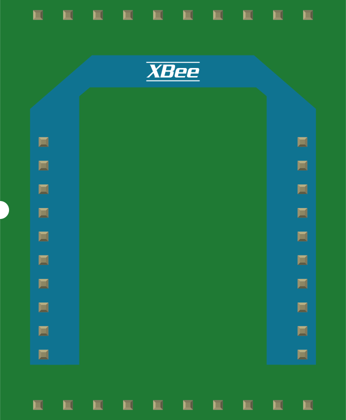
 Design with XBEE-1 in Cirkit Designer
Introduction
The XBEE-1 is a wireless communication module designed to facilitate short-range communication between devices using the Zigbee protocol. It is widely recognized for its low power consumption, robust performance, and ease of integration into various systems. The XBEE-1 is particularly popular in Internet of Things (IoT) applications, where reliable and efficient wireless communication is essential.
Explore Projects Built with XBEE-1
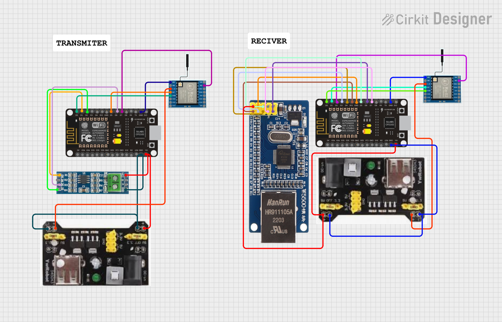 Open Project in Cirkit Designer
 Open Project in Cirkit Designer
 Open Project in Cirkit Designer
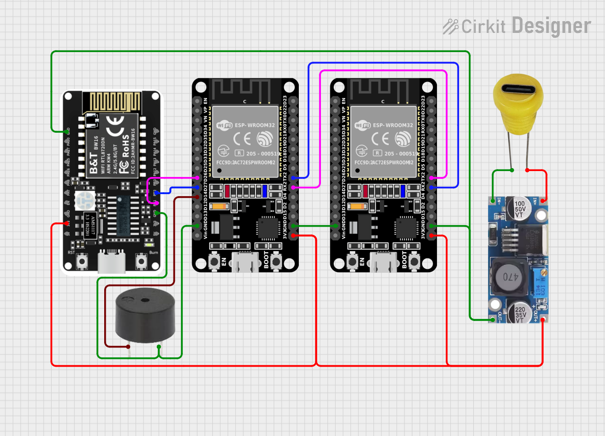 Open Project in Cirkit Designer
Explore Projects Built with XBEE-1
Open Project in Cirkit DesignerOpen Project in Cirkit DesignerOpen Project in Cirkit DesignerOpen Project in Cirkit DesignerCommon Applications and Use Cases
- Home automation systems
- Wireless sensor networks
- Industrial monitoring and control
- Smart agriculture
- Remote data logging
- Robotics and drone communication
Technical Specifications
The XBEE-1 module is built to provide reliable wireless communication with minimal power consumption. Below are its key technical specifications:
| Parameter | Specification |
|---|---|
| Communication Protocol | Zigbee (IEEE 802.15.4) |
| Operating Voltage | 2.8V to 3.3V |
| Transmit Power | 1 mW (0 dBm) |
| Receiver Sensitivity | -92 dBm |
| Data Rate | Up to 250 kbps |
| Frequency Band | 2.4 GHz ISM |
| Range (Line of Sight) | Up to 100 meters |
| Power Consumption (TX) | 45 mA |
| Power Consumption (RX) | 50 mA |
| Sleep Mode Current | < 10 µA |
| Dimensions | 24.38 mm x 27.61 mm x 2.79 mm |
| Operating Temperature | -40°C to +85°C |
Pin Configuration and Descriptions
The XBEE-1 module has a 20-pin configuration. Below is the pinout and description:
| Pin Number | Pin Name | Description |
|---|---|---|
| 1 | VCC | Power supply input (2.8V to 3.3V) |
| 2 | DOUT | UART Data Out (TX) |
| 3 | DIN | UART Data In (RX) |
| 4 | DIO12 | Digital I/O 12 |
| 5 | RESET | Reset input (active low) |
| 6 | RSSI | Signal strength indicator |
| 7 | PWM0 | PWM output or digital I/O |
| 8 | PWM1 | PWM output or digital I/O |
| 9 | DIO11 | Digital I/O 11 |
| 10 | GND | Ground |
| 11 | DIO10 | Digital I/O 10 |
| 12 | DIO9 | Digital I/O 9 |
| 13 | DIO8 | Digital I/O 8 |
| 14 | DIO7 | Digital I/O 7 |
| 15 | DIO6 | Digital I/O 6 |
| 16 | DIO5 | Digital I/O 5 |
| 17 | DIO4 | Digital I/O 4 |
| 18 | DIO3 | Digital I/O 3 |
| 19 | DIO2 | Digital I/O 2 |
| 20 | DIO1 | Digital I/O 1 |
Usage Instructions
How to Use the XBEE-1 in a Circuit
- Power Supply: Connect the VCC pin to a regulated 3.3V power source and the GND pin to ground.
- UART Communication: Use the DOUT (TX) and DIN (RX) pins to establish UART communication with a microcontroller or PC.
- Antenna: Ensure the module has a proper antenna for optimal signal strength and range.
- Configuration: Configure the XBEE-1 module using XCTU software or AT commands to set parameters like PAN ID, channel, and baud rate.
- Integration: Connect the digital I/O pins as needed for your application, such as controlling LEDs, relays, or sensors.
Important Considerations and Best Practices
- Use a level shifter if interfacing with a 5V microcontroller to avoid damaging the module.
- Place the module away from sources of interference, such as high-frequency circuits or metal enclosures.
- Ensure proper grounding to minimize noise and improve signal quality.
- Use XCTU software for easy configuration and testing of the module.
Example: Connecting XBEE-1 to Arduino UNO
Below is an example of how to connect the XBEE-1 module to an Arduino UNO and send data wirelessly:
Wiring Diagram
| XBEE-1 Pin | Arduino UNO Pin |
|---|---|
| VCC | 3.3V |
| GND | GND |
| DOUT (TX) | RX (Pin 0) |
| DIN (RX) | TX (Pin 1) |
Arduino Code
// Example code to send data from Arduino to XBEE-1 module
void setup() {
  Serial.begin(9600); // Initialize UART communication at 9600 baud
  delay(1000);        // Wait for the module to initialize
}

void loop() {
  Serial.println("Hello, XBEE!"); // Send data to XBEE-1
  delay(1000);                    // Wait 1 second before sending again
}
Troubleshooting and FAQs
Common Issues and Solutions
No Communication Between Devices
- Cause: Incorrect baud rate or mismatched PAN ID.
- Solution: Verify and configure the correct baud rate and PAN ID using XCTU software.
Short Range or Weak Signal
- Cause: Poor antenna placement or interference.
- Solution: Ensure the antenna is properly connected and placed away from interference sources.
Module Not Responding
- Cause: Incorrect power supply or damaged module.
- Solution: Check the power supply voltage and connections. Replace the module if necessary.
Data Loss or Corruption
- Cause: High noise environment or incorrect UART settings.
- Solution: Use proper shielding and verify UART settings (baud rate, parity, etc.).
FAQs
Q1: Can the XBEE-1 communicate with other Zigbee devices?
A1: Yes, the XBEE-1 is compatible with other Zigbee devices as long as they share the same PAN ID and channel.
Q2: How do I reset the XBEE-1 module?
A2: Pull the RESET pin low for at least 200 ms and then release it to reset the module.
Q3: Can I use the XBEE-1 with a 5V microcontroller?
A3: Yes, but you must use a level shifter to convert the 5V signals to 3.3V to avoid damaging the module.
Q4: What is the maximum number of devices in a Zigbee network?
A4: A Zigbee network can support up to 65,000 devices, but practical limits depend on the application and network design.