Cirkit Designer Logo
Cirkit Designer
Your all-in-one circuit design IDE
Home / 
Component Documentation

How to Use FeeTech STS3032: Examples, Pinouts, and Specs
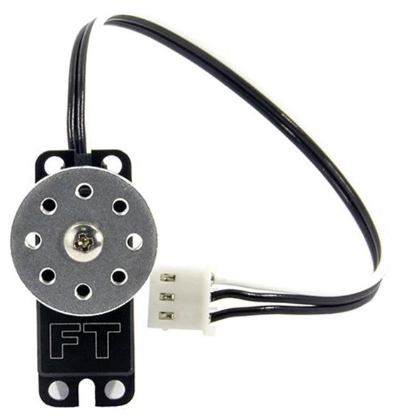
Image of FeeTech STS3032
Cirkit Designer LogoDesign with FeeTech STS3032 in Cirkit Designer

Introduction

The FeeTech STS3032 is a high-precision temperature and humidity sensor designed for accurate environmental monitoring. It provides a digital output, making it easy to integrate into a wide range of electronic systems. With its compact design and reliable performance, the STS3032 is ideal for applications such as HVAC systems, weather stations, smart home devices, and industrial automation.

Explore Projects Built with FeeTech STS3032

Use Cirkit Designer to design, explore, and prototype these projects online. Some projects support real-time simulation. Click "Open Project" to start designing instantly!
Satellite-Based Timing and Navigation System with SDR and Atomic Clock Synchronization
Image of GPS 시스템 측정 구성도_Confirm: A project utilizing FeeTech STS3032 in a practical application
This circuit appears to be a complex system involving power supply management, GPS and timing synchronization, and data communication. It includes a SI-TEX G1 Satellite Compass for GPS data, an XHTF1021 Atomic Rubidium Clock for precise timing, and Ettus USRP B200 units for software-defined radio communication. Power is supplied through various SMPS units and distributed via terminal blocks and DC jacks. Data communication is facilitated by Beelink MINI S12 N95 computers, RS232 splitters, and a 1000BASE-T Media Converter for network connectivity. RF Directional Couplers are used to interface antennas with the USRP units, and the entire system is likely contained within cases for protection and organization.
Cirkit Designer LogoOpen Project in Cirkit Designer
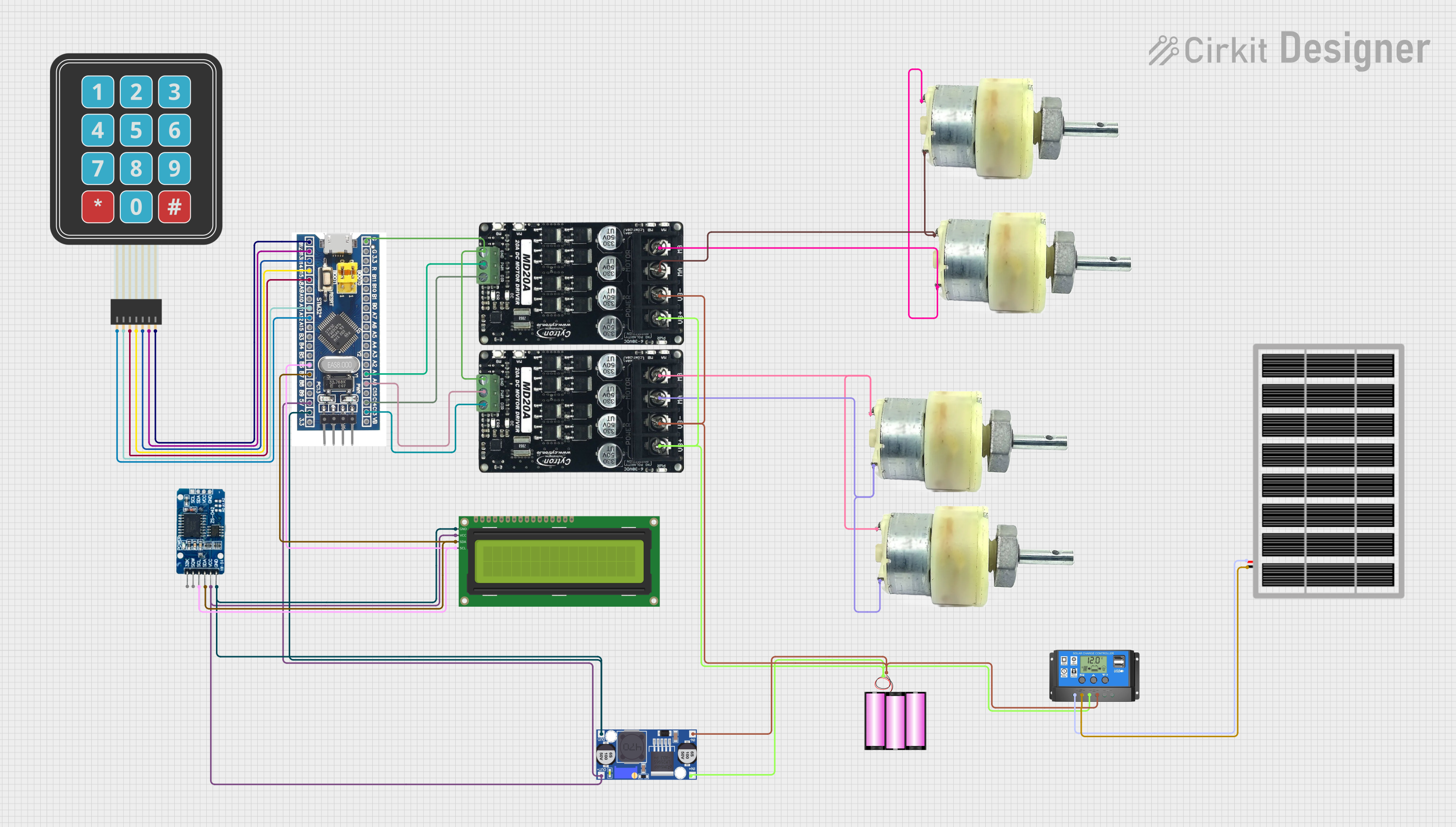
Solar-Powered STM32-Based Automation System with Matrix Keypad and RTC
Image of soloar cleaner : A project utilizing FeeTech STS3032 in a practical application
This circuit features an STM32F103C8T6 microcontroller interfaced with a membrane matrix keypad for input, an RTC DS3231 for real-time clock functionality, and a 16x2 I2C LCD for display. It controls four 12V geared motors through two MD20 CYTRON motor drivers, with the motor power supplied by a 12V battery regulated by a buck converter. The battery is charged via a solar panel connected through a solar charge controller, ensuring a renewable energy source for the system.
Cirkit Designer LogoOpen Project in Cirkit Designer
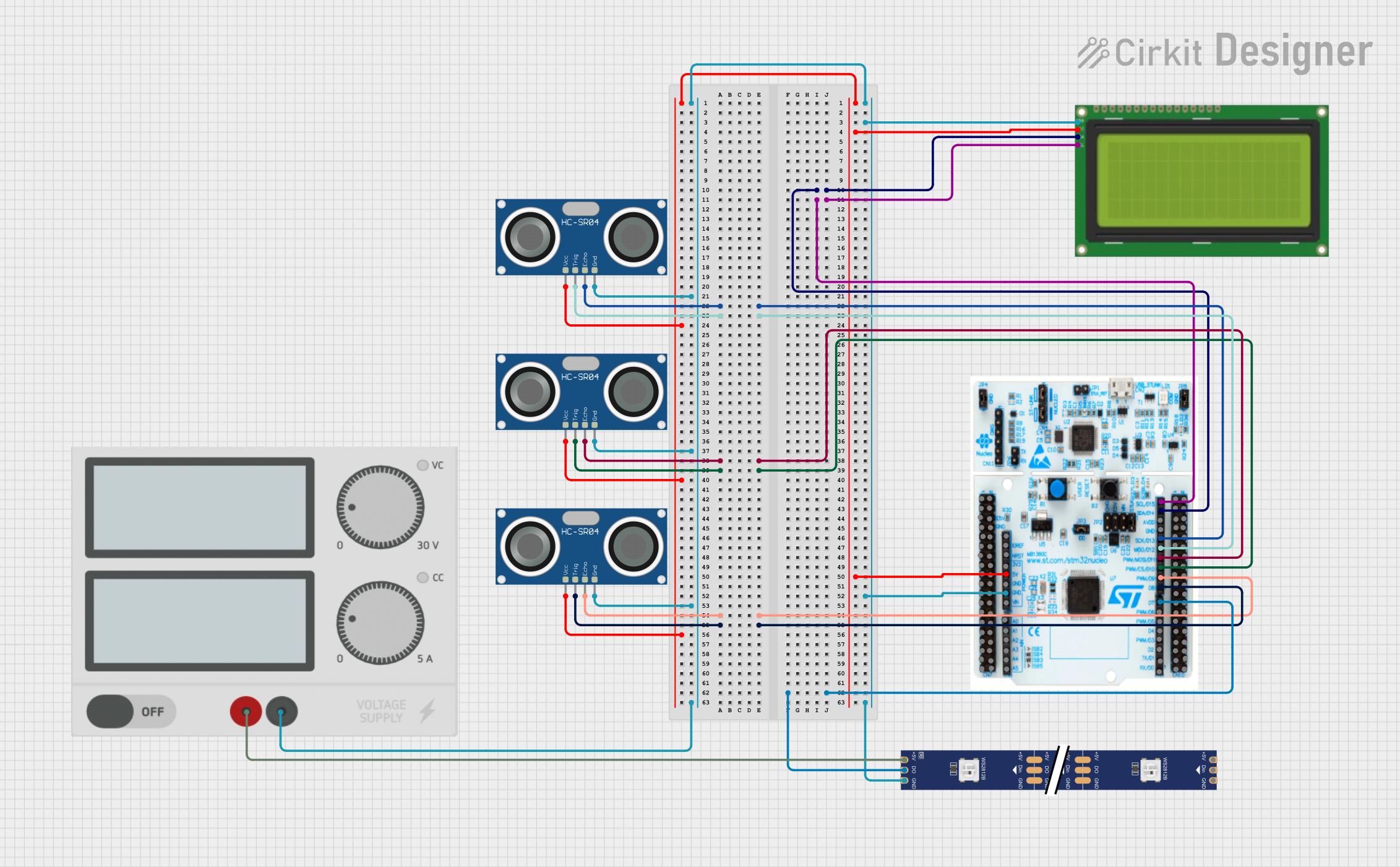
STM32 Nucleo F303RE Controlled Ultrasonic Sensing with RGB Feedback and I2C LCD Display
Image of CS435-final: A project utilizing FeeTech STS3032 in a practical application
This circuit features a STM32 Nucleo F303RE microcontroller interfaced with three HC-SR04 ultrasonic sensors for distance measurement and a 20x4 LCD display over I2C for data output. Additionally, there is a WS2812 RGB LED strip controlled by the microcontroller for visual feedback. The power supply provides a common 5V to the LCD, ultrasonic sensors, LED strip, and the microcontroller's +5V input, with all components sharing a common ground.
Cirkit Designer LogoOpen Project in Cirkit Designer
Arduino Mega 2560 Based Security System with Fingerprint Authentication and SMS Alerts
Image of Door security system: A project utilizing FeeTech STS3032 in a practical application
This circuit features an Arduino Mega 2560 microcontroller interfaced with a SIM800L GSM module, two fingerprint scanners, an I2C LCD display, an IR sensor, and a piezo buzzer. Power management is handled by a PowerBoost 1000 Basic Pad USB, a TP4056 charging module, and a Li-ion 18650 battery, with an option to use a Mini AC-DC 110V-230V to 5V 700mA module for direct power supply. The primary functionality appears to be a security system with GSM communication capabilities, biometric access control, and visual/audible feedback.
Cirkit Designer LogoOpen Project in Cirkit Designer

Explore Projects Built with FeeTech STS3032

Use Cirkit Designer to design, explore, and prototype these projects online. Some projects support real-time simulation. Click "Open Project" to start designing instantly!
Image of GPS 시스템 측정 구성도_Confirm: A project utilizing FeeTech STS3032 in a practical application
Satellite-Based Timing and Navigation System with SDR and Atomic Clock Synchronization
This circuit appears to be a complex system involving power supply management, GPS and timing synchronization, and data communication. It includes a SI-TEX G1 Satellite Compass for GPS data, an XHTF1021 Atomic Rubidium Clock for precise timing, and Ettus USRP B200 units for software-defined radio communication. Power is supplied through various SMPS units and distributed via terminal blocks and DC jacks. Data communication is facilitated by Beelink MINI S12 N95 computers, RS232 splitters, and a 1000BASE-T Media Converter for network connectivity. RF Directional Couplers are used to interface antennas with the USRP units, and the entire system is likely contained within cases for protection and organization.
Cirkit Designer LogoOpen Project in Cirkit Designer
Image of soloar cleaner : A project utilizing FeeTech STS3032 in a practical application
Solar-Powered STM32-Based Automation System with Matrix Keypad and RTC
This circuit features an STM32F103C8T6 microcontroller interfaced with a membrane matrix keypad for input, an RTC DS3231 for real-time clock functionality, and a 16x2 I2C LCD for display. It controls four 12V geared motors through two MD20 CYTRON motor drivers, with the motor power supplied by a 12V battery regulated by a buck converter. The battery is charged via a solar panel connected through a solar charge controller, ensuring a renewable energy source for the system.
Cirkit Designer LogoOpen Project in Cirkit Designer
Image of CS435-final: A project utilizing FeeTech STS3032 in a practical application
STM32 Nucleo F303RE Controlled Ultrasonic Sensing with RGB Feedback and I2C LCD Display
This circuit features a STM32 Nucleo F303RE microcontroller interfaced with three HC-SR04 ultrasonic sensors for distance measurement and a 20x4 LCD display over I2C for data output. Additionally, there is a WS2812 RGB LED strip controlled by the microcontroller for visual feedback. The power supply provides a common 5V to the LCD, ultrasonic sensors, LED strip, and the microcontroller's +5V input, with all components sharing a common ground.
Cirkit Designer LogoOpen Project in Cirkit Designer
Image of Door security system: A project utilizing FeeTech STS3032 in a practical application
Arduino Mega 2560 Based Security System with Fingerprint Authentication and SMS Alerts
This circuit features an Arduino Mega 2560 microcontroller interfaced with a SIM800L GSM module, two fingerprint scanners, an I2C LCD display, an IR sensor, and a piezo buzzer. Power management is handled by a PowerBoost 1000 Basic Pad USB, a TP4056 charging module, and a Li-ion 18650 battery, with an option to use a Mini AC-DC 110V-230V to 5V 700mA module for direct power supply. The primary functionality appears to be a security system with GSM communication capabilities, biometric access control, and visual/audible feedback.
Cirkit Designer LogoOpen Project in Cirkit Designer

Common Applications

  • HVAC (Heating, Ventilation, and Air Conditioning) systems
  • Weather monitoring stations
  • Smart home automation
  • Industrial environmental monitoring
  • IoT (Internet of Things) devices

Technical Specifications

The FeeTech STS3032 is engineered for precision and reliability. Below are its key technical specifications:

Parameter Value
Operating Voltage 3.3V to 5.5V
Operating Current 2.5mA (typical)
Temperature Range -40°C to +125°C
Temperature Accuracy ±0.3°C (typical)
Humidity Range 0% to 100% RH
Humidity Accuracy ±2% RH (typical)
Communication Protocol I²C
I²C Address 0x40 (default)
Response Time <1 second
Dimensions 10mm x 10mm x 3mm

Pin Configuration

The STS3032 has a 4-pin interface for easy connection to microcontrollers and other devices. Below is the pinout description:

Pin Name Description
1 VCC Power supply input (3.3V to 5.5V)
2 GND Ground connection
3 SDA I²C data line
4 SCL I²C clock line

Usage Instructions

Connecting the STS3032 to a Circuit

  1. Power Supply: Connect the VCC pin to a 3.3V or 5V power source and the GND pin to the ground.
  2. I²C Communication: Connect the SDA and SCL pins to the corresponding I²C pins on your microcontroller. Use pull-up resistors (typically 4.7kΩ) on the SDA and SCL lines if not already present in your circuit.
  3. Address Configuration: The default I²C address is 0x40. Ensure no other devices on the I²C bus share this address.

Important Considerations

  • Avoid exposing the sensor to extreme conditions (e.g., condensation, high humidity for prolonged periods) to maintain accuracy.
  • Place the sensor in a location with good airflow for accurate readings.
  • Use decoupling capacitors (e.g., 0.1µF) near the VCC pin to reduce noise.

Example: Using the STS3032 with Arduino UNO

Below is an example of how to interface the STS3032 with an Arduino UNO using the Wire library for I²C communication.

#include <Wire.h>

// I2C address of the STS3032 sensor
#define STS3032_ADDRESS 0x40

void setup() {
  Wire.begin(); // Initialize I2C communication
  Serial.begin(9600); // Start serial communication for debugging
  Serial.println("STS3032 Sensor Initialization...");
}

void loop() {
  Wire.beginTransmission(STS3032_ADDRESS); // Start communication with sensor
  Wire.write(0xE3); // Command to read temperature
  Wire.endTransmission();
  delay(50); // Wait for sensor to process the command

  Wire.requestFrom(STS3032_ADDRESS, 2); // Request 2 bytes of data
  if (Wire.available() == 2) {
    uint16_t rawData = (Wire.read() << 8) | Wire.read(); // Combine two bytes
    float temperature = -46.85 + (175.72 * rawData / 65536.0); // Convert to °C
    Serial.print("Temperature: ");
    Serial.print(temperature);
    Serial.println(" °C");
  }

  delay(1000); // Wait 1 second before the next reading
}

Notes on the Code

  • The 0xE3 command is used to read the temperature. Refer to the sensor's datasheet for additional commands (e.g., for humidity readings).
  • Ensure the I²C pull-up resistors are properly connected for reliable communication.

Troubleshooting and FAQs

Common Issues

  1. No Data from the Sensor

    • Ensure the sensor is powered correctly (check VCC and GND connections).
    • Verify the I²C address (default is 0x40) and ensure no address conflicts on the bus.
    • Check the pull-up resistors on the SDA and SCL lines.
  2. Inaccurate Readings

    • Ensure the sensor is not exposed to condensation or extreme environmental conditions.
    • Verify that the sensor is placed in an area with good airflow.
    • Check for noise in the power supply and add decoupling capacitors if necessary.
  3. I²C Communication Errors

    • Confirm the SDA and SCL lines are connected to the correct pins on the microcontroller.
    • Check the I²C clock speed; the STS3032 supports standard (100kHz) and fast (400kHz) modes.

FAQs

Q: Can the STS3032 measure both temperature and humidity simultaneously?
A: Yes, the sensor can measure both parameters, but you need to send separate commands for each measurement.

Q: What is the maximum cable length for I²C communication with the STS3032?
A: The maximum cable length depends on the pull-up resistor values and the I²C clock speed. For standard mode (100kHz), a length of up to 1 meter is typically reliable.

Q: Is the STS3032 waterproof?
A: No, the sensor is not waterproof. Avoid exposing it to water or condensation to maintain accuracy and longevity.

Q: Can I use the STS3032 with a 3.3V microcontroller?
A: Yes, the sensor operates within a voltage range of 3.3V to 5.5V, making it compatible with both 3.3V and 5V systems.