
How to Use bigreetech TMC5160: Examples, Pinouts, and Specs
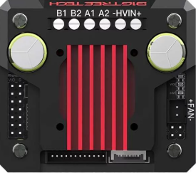
 Design with bigreetech TMC5160 in Cirkit Designer
Introduction
The Bigtreetech TMC5160 is a high-performance stepper motor driver designed for precise and efficient control of stepper motors. It features advanced microstepping capabilities, enabling smooth motor operation with minimal noise and vibration. The TMC5160 supports multiple modes of operation, including stealthChop for ultra-quiet performance and spreadCycle for high torque at higher speeds. Additionally, it offers features such as stall detection, current control, and diagnostics, making it an ideal choice for applications requiring precision and reliability.
Explore Projects Built with bigreetech TMC5160
 Open Project in Cirkit Designer
 Open Project in Cirkit Designer
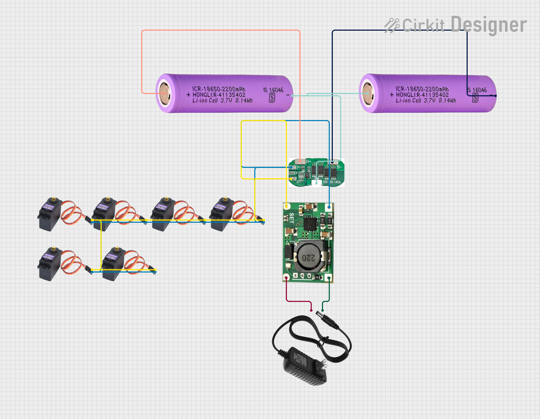 Open Project in Cirkit Designer
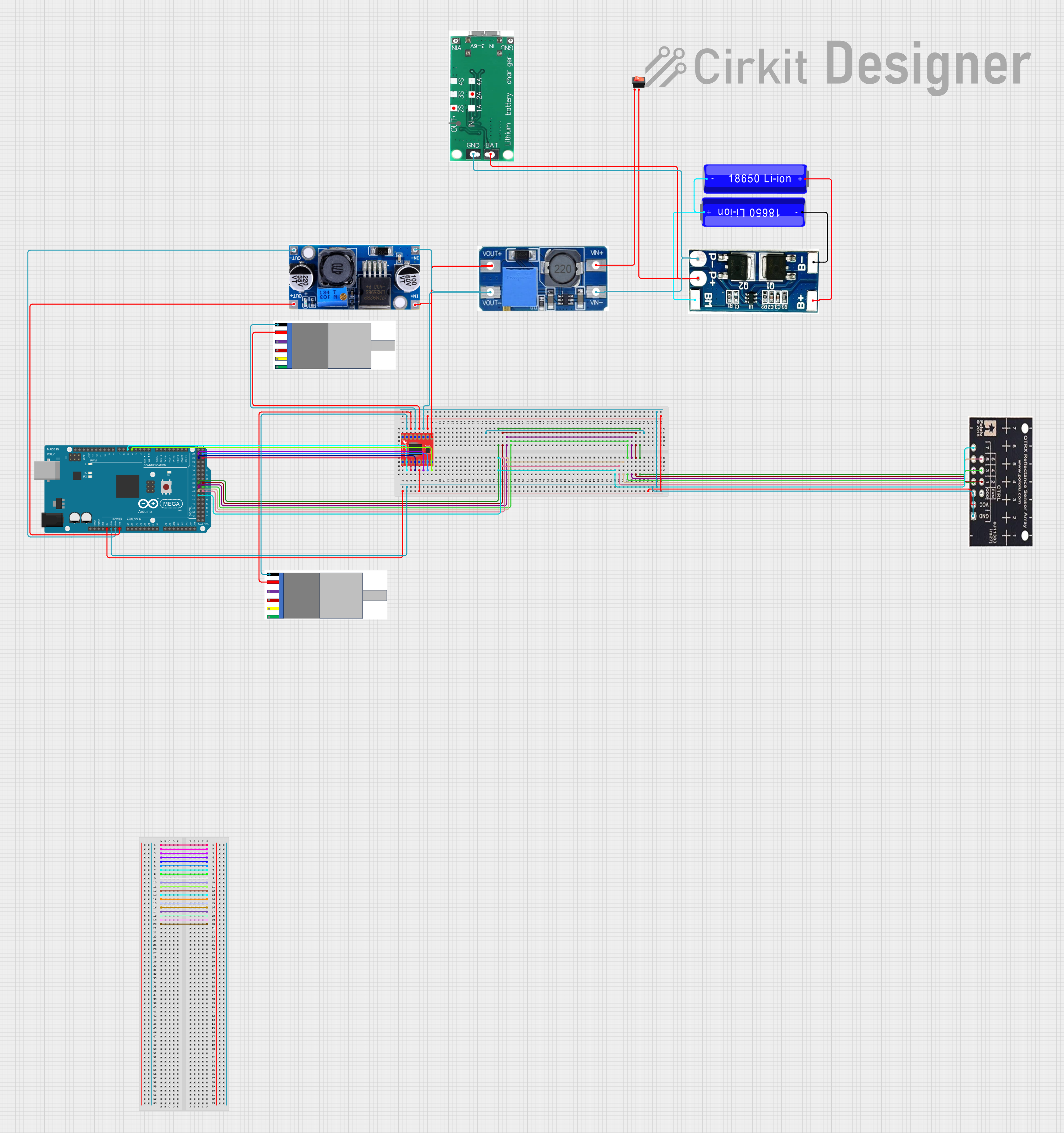 Open Project in Cirkit Designer
Explore Projects Built with bigreetech TMC5160
Open Project in Cirkit DesignerOpen Project in Cirkit DesignerOpen Project in Cirkit DesignerOpen Project in Cirkit DesignerCommon Applications
- 3D printers
- CNC machines
- Robotics
- Automated conveyor systems
- Laser cutters and engravers
Technical Specifications
Key Technical Details
| Parameter | Value |
|---|---|
| Supply Voltage (VM) | 8V to 60V |
| Logic Voltage (VIO) | 3.3V or 5V |
| Maximum Motor Current | Up to 20A peak (with proper cooling) |
| Microstepping Resolution | Up to 256 microsteps per full step |
| Communication Interface | SPI |
| Operating Modes | stealthChop, spreadCycle, stallGuard, coolStep |
| Integrated Features | Stall detection, current scaling, diagnostics |
Pin Configuration and Descriptions
The TMC5160 is typically used in a breakout board format. Below is a table of the key pins and their functions:
| Pin Name | Description |
|---|---|
| VM | Motor power supply input (8V to 60V). |
| GND | Ground connection. |
| VIO | Logic voltage input (3.3V or 5V). |
| ENN | Enable pin (active low). Disables the driver when pulled high. |
| DIR | Direction input. Determines the rotation direction of the stepper motor. |
| STEP | Step pulse input. Each pulse advances the motor by one microstep. |
| CSN | Chip select for SPI communication (active low). |
| SCK | SPI clock input. |
| SDI | SPI data input. |
| SDO | SPI data output. |
| DIAG0/DIAG1 | Diagnostic outputs for stall detection and other status signals. |
| CLK | External clock input (optional). |
| A1, A2, B1, B2 | Motor coil connections. |
Usage Instructions
How to Use the TMC5160 in a Circuit
- Power Supply: Connect the motor power supply (VM) to the VM pin, ensuring it is within the 8V to 60V range. Connect the ground (GND) pin to the power supply ground.
- Logic Voltage: Provide a 3.3V or 5V logic voltage to the VIO pin, depending on your microcontroller's logic level.
- Motor Connections: Connect the stepper motor coils to the A1, A2, B1, and B2 pins. Ensure the wiring matches the motor's datasheet.
- Control Signals: Connect the STEP and DIR pins to your microcontroller for step and direction control. Use the ENN pin to enable or disable the driver.
- SPI Communication: Connect the CSN, SCK, SDI, and SDO pins to your microcontroller's SPI interface for configuration and diagnostics.
- Cooling: Ensure proper cooling, such as a heatsink or fan, to handle high currents and prevent overheating.
Important Considerations
- Microstepping Configuration: Use SPI to configure the microstepping resolution and other parameters. The default resolution is typically 256 microsteps per full step.
- Stall Detection: Enable stallGuard via SPI to detect motor stalls and protect the motor and driver.
- Silent Operation: Use stealthChop mode for applications requiring quiet operation, such as 3D printers.
- Current Limiting: Set the motor current limit via SPI to prevent overheating and ensure safe operation.
Example Code for Arduino UNO
Below is an example of how to configure and control the TMC5160 using an Arduino UNO:
#include <SPI.h>

// Define SPI pins for Arduino UNO
#define CS_PIN 10  // Chip Select pin
#define STEP_PIN 3 // Step pin
#define DIR_PIN 2  // Direction pin

void setup() {
  // Initialize SPI
  SPI.begin();
  pinMode(CS_PIN, OUTPUT);
  digitalWrite(CS_PIN, HIGH); // Set CS pin high (inactive)

  // Initialize STEP and DIR pins
  pinMode(STEP_PIN, OUTPUT);
  pinMode(DIR_PIN, OUTPUT);

  // Configure TMC5160 via SPI
  configureTMC5160();
}

void loop() {
  // Example: Rotate motor in one direction
  digitalWrite(DIR_PIN, HIGH); // Set direction
  for (int i = 0; i < 200; i++) { // 200 steps
    digitalWrite(STEP_PIN, HIGH);
    delayMicroseconds(500); // Adjust for desired speed
    digitalWrite(STEP_PIN, LOW);
    delayMicroseconds(500);
  }

  delay(1000); // Pause for 1 second

  // Reverse direction
  digitalWrite(DIR_PIN, LOW);
  for (int i = 0; i < 200; i++) {
    digitalWrite(STEP_PIN, HIGH);
    delayMicroseconds(500);
    digitalWrite(STEP_PIN, LOW);
    delayMicroseconds(500);
  }

  delay(1000); // Pause for 1 second
}

void configureTMC5160() {
  // Example SPI configuration for TMC5160
  digitalWrite(CS_PIN, LOW); // Select TMC5160
  SPI.transfer(0x80); // Write to GCONF register (example address)
  SPI.transfer(0x00); // Example data: Disable stealthChop
  digitalWrite(CS_PIN, HIGH); // Deselect TMC5160
}
Troubleshooting and FAQs
Common Issues and Solutions
Motor Not Moving:
- Check the power supply voltage (VM) and ensure it is within the specified range.
- Verify the motor connections (A1, A2, B1, B2) and ensure they match the motor's datasheet.
- Ensure the STEP and DIR signals are being sent correctly from the microcontroller.
Overheating:
- Ensure proper cooling with a heatsink or fan.
- Reduce the motor current limit via SPI configuration.
Noisy Operation:
- Enable stealthChop mode for quieter operation.
- Check for loose motor connections or mechanical issues.
Stall Detection Not Working:
- Ensure stallGuard is enabled via SPI.
- Verify that the motor current is set correctly for the load.
FAQs
Q: Can the TMC5160 be used with 12V stepper motors?
A: Yes, the TMC5160 supports motor supply voltages from 8V to 60V, making it compatible with 12V stepper motors.
Q: How do I enable microstepping?
A: Microstepping is configured via SPI. The TMC5160 supports up to 256 microsteps per full step.
Q: What is the difference between stealthChop and spreadCycle?
A: stealthChop is optimized for silent operation, while spreadCycle provides higher torque at higher speeds.
Q: Do I need an external clock for the TMC5160?
A: No, the TMC5160 has an internal clock, but you can use an external clock if required for synchronization.