Cirkit Designer Logo
Cirkit Designer
Your all-in-one circuit design IDE
Home / 
Component Documentation

How to Use 12v~40v 10A PWM DC Motor Speed Controller: Examples, Pinouts, and Specs

Image of 12v~40v 10A PWM DC Motor Speed Controller
Cirkit Designer LogoDesign with 12v~40v 10A PWM DC Motor Speed Controller in Cirkit Designer

Introduction

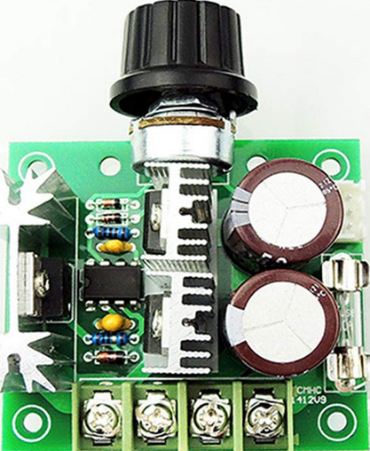
The HiLetgo 12V~40V 10A PWM DC Motor Speed Controller is an electronic device designed to control the speed of a DC motor by adjusting the voltage delivered to the motor using Pulse-Width Modulation (PWM). This method of speed control is efficient and results in less heat generation compared to resistive speed control methods. The controller is suitable for a wide range of applications, including fan speed control, conveyor systems, or any application where variable speed control of a DC motor is required.

Explore Projects Built with 12v~40v 10A PWM DC Motor Speed Controller

Use Cirkit Designer to design, explore, and prototype these projects online. Some projects support real-time simulation. Click "Open Project" to start designing instantly!
12V PWM-Controlled Water Pump System
Image of moter speed controller: A project utilizing 12v~40v 10A PWM DC Motor Speed Controller in a practical application
This circuit is designed to control the speed of a water pump using a PWM DC motor speed controller. The 12V5Ah battery provides power to the speed controller, which in turn regulates the power supplied to the water pump, allowing for adjustable flow rates. There is no microcontroller code provided, indicating that the speed control is likely adjusted manually via the PWM controller.
Cirkit Designer LogoOpen Project in Cirkit Designer
Dual DC Motor Control Circuit with Speed Regulation and Indicator Lamp
Image of egg peeling machine: A project utilizing 12v~40v 10A PWM DC Motor Speed Controller in a practical application
This circuit includes a 12V 200Ah battery that powers a water pump and two DC motors, each controlled by a separate 12v~40v 10A PWM DC motor speed controller. A rocker switch (SPST) is used to control the power flow to the water pump and a pilot lamp indicates when the pump is powered. The DC motors' speed can be adjusted by the PWM controllers, and wire connectors are used to organize the connections between components.
Cirkit Designer LogoOpen Project in Cirkit Designer
PWM-Controlled DC Motor Speed Regulator with DC Barrel Jack Power Input
Image of Siren: A project utilizing 12v~40v 10A PWM DC Motor Speed Controller in a practical application
This circuit controls the speed of a DC motor using a 12V PWM speed controller. Power is supplied to the speed controller through a 2.1mm DC barrel jack, which then modulates the voltage and current to the motor's terminals to adjust its speed. There is no microcontroller code involved, indicating that the speed control is likely adjusted manually via the speed controller's onboard settings.
Cirkit Designer LogoOpen Project in Cirkit Designer
Battery-Powered DC Motor Control System with Speed Regulation
Image of wheel chair: A project utilizing 12v~40v 10A PWM DC Motor Speed Controller in a practical application
This circuit is a motor control system powered by two 12V batteries connected in series, with a 3-position switch to control a PWM motor speed controller. The system includes a pilot lamp for status indication and a NI-MH battery charger powered by an AC source.
Cirkit Designer LogoOpen Project in Cirkit Designer

Explore Projects Built with 12v~40v 10A PWM DC Motor Speed Controller

Use Cirkit Designer to design, explore, and prototype these projects online. Some projects support real-time simulation. Click "Open Project" to start designing instantly!
Image of moter speed controller: A project utilizing 12v~40v 10A PWM DC Motor Speed Controller in a practical application
12V PWM-Controlled Water Pump System
This circuit is designed to control the speed of a water pump using a PWM DC motor speed controller. The 12V5Ah battery provides power to the speed controller, which in turn regulates the power supplied to the water pump, allowing for adjustable flow rates. There is no microcontroller code provided, indicating that the speed control is likely adjusted manually via the PWM controller.
Cirkit Designer LogoOpen Project in Cirkit Designer
Image of egg peeling machine: A project utilizing 12v~40v 10A PWM DC Motor Speed Controller in a practical application
Dual DC Motor Control Circuit with Speed Regulation and Indicator Lamp
This circuit includes a 12V 200Ah battery that powers a water pump and two DC motors, each controlled by a separate 12v~40v 10A PWM DC motor speed controller. A rocker switch (SPST) is used to control the power flow to the water pump and a pilot lamp indicates when the pump is powered. The DC motors' speed can be adjusted by the PWM controllers, and wire connectors are used to organize the connections between components.
Cirkit Designer LogoOpen Project in Cirkit Designer
Image of Siren: A project utilizing 12v~40v 10A PWM DC Motor Speed Controller in a practical application
PWM-Controlled DC Motor Speed Regulator with DC Barrel Jack Power Input
This circuit controls the speed of a DC motor using a 12V PWM speed controller. Power is supplied to the speed controller through a 2.1mm DC barrel jack, which then modulates the voltage and current to the motor's terminals to adjust its speed. There is no microcontroller code involved, indicating that the speed control is likely adjusted manually via the speed controller's onboard settings.
Cirkit Designer LogoOpen Project in Cirkit Designer
Image of wheel chair: A project utilizing 12v~40v 10A PWM DC Motor Speed Controller in a practical application
Battery-Powered DC Motor Control System with Speed Regulation
This circuit is a motor control system powered by two 12V batteries connected in series, with a 3-position switch to control a PWM motor speed controller. The system includes a pilot lamp for status indication and a NI-MH battery charger powered by an AC source.
Cirkit Designer LogoOpen Project in Cirkit Designer

Technical Specifications

Key Technical Details

  • Input Voltage: 12V to 40V DC
  • Output Voltage: Linear under load
  • Continuous Current: Up to 10A
  • Max Current: 10A (without a heat sink)
  • PWM Frequency: 13kHz
  • Duty Cycle Adjustable: 0%-100%
  • Control Power: 0.01-400W
  • Static Current: 0.02 A (Standby)
  • PWM Pulse Width Speed Range: 10%-100%
  • Operating Temperature: -20 to +40°C
  • Dimensions: 73 x 60 x 27 mm

Pin Configuration and Descriptions

Pin Number Description Notes
1 Motor Output (+) Connect to DC motor positive lead
2 Motor Output (-) Connect to DC motor negative lead
3 Power Supply Input (+) Connect to positive terminal of DC power supply
4 Power Supply Input (-) Connect to negative terminal of DC power supply
5 Speed Control Potentiometer Turn to adjust motor speed

Usage Instructions

How to Use the Component in a Circuit

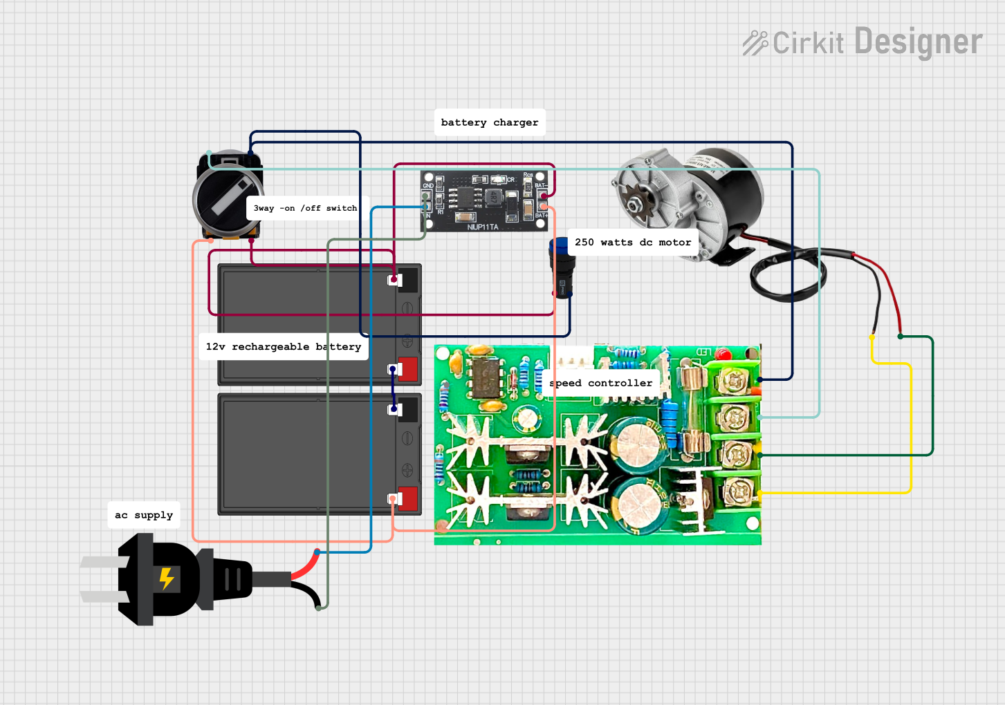
  1. Power Supply Connection: Connect a DC power supply to the controller's input terminals, ensuring that the voltage is within the specified range (12V to 40V). Observe correct polarity.

  2. Motor Connection: Connect the DC motor to the controller's output terminals. Again, ensure correct polarity.

  3. Speed Adjustment: Use the onboard potentiometer to adjust the motor speed. Turning it clockwise will increase the speed, while turning it counter-clockwise will decrease it.

Important Considerations and Best Practices

  • Heat Dissipation: For currents above 10A, it is recommended to use a heat sink to dissipate heat and prevent overheating.

  • Motor Ratings: Ensure that the motor's voltage and current ratings are compatible with the controller's specifications.

  • PWM Frequency: Be aware that some motors may produce an audible whine at certain PWM frequencies. This is normal but can be minimized by choosing a motor with a suitable frequency response.

  • Safety: Always disconnect power before making or changing connections to prevent accidental shorts or component damage.

Troubleshooting and FAQs

Common Issues

  • Motor Not Turning: Check all connections for proper contact and correct polarity. Ensure that the power supply is within the specified voltage range and that the motor is functioning correctly.

  • Overheating: If the controller is overheating, reduce the load or attach a heat sink to the controller.

  • Inconsistent Speed Control: Ensure that the potentiometer is not damaged and that the PWM frequency is compatible with the motor.

Solutions and Tips for Troubleshooting

  • Check Connections: Loose connections can cause intermittent operation. Ensure all connections are secure.

  • Test Power Supply: Verify that the power supply is delivering the correct voltage and is capable of supplying sufficient current.

  • Inspect for Damage: Look for any visible signs of damage to the controller, such as burnt components or traces.

FAQs

Q: Can I use this controller with a 24V motor? A: Yes, as long as the motor's current rating does not exceed 10A.

Q: What is the maximum frequency of PWM this controller can handle? A: The controller operates at a fixed PWM frequency of 13kHz.

Q: Can I use this controller with an Arduino? A: Yes, you can use an Arduino to control the potentiometer or to switch the power supply to the controller on and off, but direct PWM control from the Arduino is not supported by this controller.

Example Arduino Code

// Example code to turn the motor on and off using an Arduino
int motorControlPin = 3; // Connect to the power supply input of the controller

void setup() {
  pinMode(motorControlPin, OUTPUT);
}

void loop() {
  digitalWrite(motorControlPin, HIGH); // Turn on the motor
  delay(5000);                         // Run for 5 seconds
  digitalWrite(motorControlPin, LOW);  // Turn off the motor
  delay(5000);                         // Wait for 5 seconds
}

Note: This code example simply turns the motor on and off by controlling the power supply to the motor controller. The actual speed control is still done using the onboard potentiometer.