How to Use ESP wroom 32 (30 pines): Examples, Pinouts, and Specs
Introduction
The ESP-WROOM-32 is a powerful microcontroller module designed for IoT (Internet of Things) applications. It features built-in Wi-Fi and Bluetooth capabilities, making it ideal for wireless communication and control. With 30 GPIO (General Purpose Input/Output) pins, the ESP-WROOM-32 offers versatile connectivity options for sensors, actuators, and other peripherals. Its compact size and robust performance make it a popular choice for smart home devices, industrial automation, and wearable technology.
Explore Projects Built with ESP wroom 32 (30 pines)


Explore Projects Built with ESP wroom 32 (30 pines)
Common Applications
- Smart home automation (e.g., lighting, thermostats, security systems)
- IoT devices and wireless sensor networks
- Wearable technology
- Industrial automation and control systems
- Robotics and remote monitoring systems
Technical Specifications
Key Technical Details
- Microcontroller: Tensilica Xtensa LX6 dual-core processor
- Clock Speed: Up to 240 MHz
- Flash Memory: 4 MB (external)
- RAM: 520 KB SRAM
- Wi-Fi: 802.11 b/g/n (2.4 GHz)
- Bluetooth: v4.2 BR/EDR and BLE
- Operating Voltage: 3.3V
- GPIO Pins: 30 (multipurpose, including ADC, DAC, PWM, I2C, SPI, UART)
- ADC Channels: 18 (12-bit resolution)
- DAC Channels: 2
- Operating Temperature: -40°C to 85°C
- Power Consumption: Ultra-low power in deep sleep mode (~10 µA)
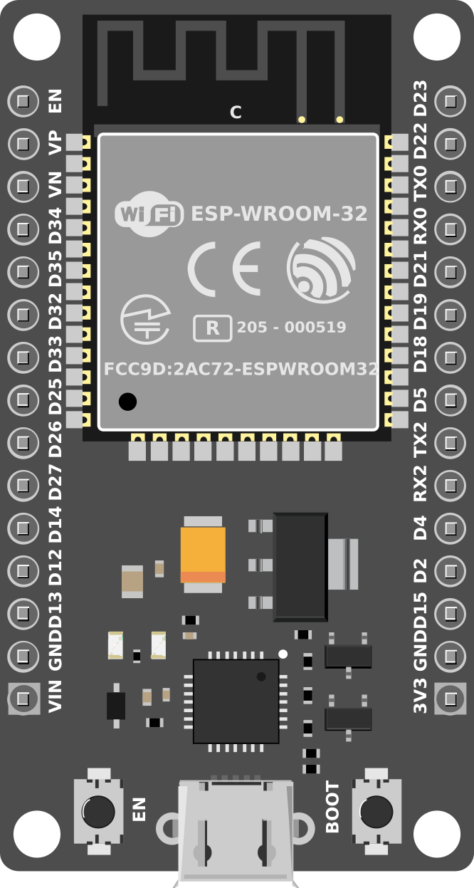
Pin Configuration and Descriptions
The ESP-WROOM-32 module has 30 pins, each with specific functions. Below is the pinout description:
| Pin Number | Pin Name | Function |
|---|---|---|
| 1 | EN | Enable pin (active high, resets the chip when pulled low) |
| 2 | IO0 | GPIO0, used for boot mode selection (must be low for flashing) |
| 3 | IO1 (TX0) | GPIO1, UART0 TX (serial communication) |
| 4 | IO3 (RX0) | GPIO3, UART0 RX (serial communication) |
| 5 | IO4 | GPIO4, general-purpose I/O |
| 6 | IO5 | GPIO5, general-purpose I/O |
| 7 | IO12 | GPIO12, ADC2 channel 5, HSPI MISO |
| 8 | IO13 | GPIO13, ADC2 channel 4, HSPI MOSI |
| 9 | IO14 | GPIO14, ADC2 channel 6, HSPI CLK |
| 10 | IO15 | GPIO15, ADC2 channel 3, HSPI CS |
| 11 | IO16 | GPIO16, general-purpose I/O, RTC GPIO |
| 12 | IO17 | GPIO17, general-purpose I/O, RTC GPIO |
| 13 | IO18 | GPIO18, VSPI CLK |
| 14 | IO19 | GPIO19, VSPI MISO |
| 15 | IO21 | GPIO21, I2C SDA |
| 16 | IO22 | GPIO22, I2C SCL |
| 17 | IO23 | GPIO23, VSPI MOSI |
| 18 | IO25 | GPIO25, DAC1, ADC2 channel 8 |
| 19 | IO26 | GPIO26, DAC2, ADC2 channel 9 |
| 20 | IO27 | GPIO27, ADC2 channel 7 |
| 21 | IO32 | GPIO32, ADC1 channel 4, touch sensor T9 |
| 22 | IO33 | GPIO33, ADC1 channel 5, touch sensor T8 |
| 23 | IO34 | GPIO34, ADC1 channel 6 (input only) |
| 24 | IO35 | GPIO35, ADC1 channel 7 (input only) |
| 25 | GND | Ground |
| 26 | 3V3 | 3.3V power supply |
| 27 | VIN | Input voltage (5V recommended for onboard regulator) |
| 28 | IO36 | GPIO36, ADC1 channel 0, touch sensor T0 (input only) |
| 29 | IO39 | GPIO39, ADC1 channel 3, touch sensor T3 (input only) |
| 30 | RST | Reset pin (active low) |
Usage Instructions
How to Use the ESP-WROOM-32 in a Circuit
Powering the Module:
- Connect the
3V3pin to a 3.3V power source. Alternatively, you can use theVINpin with a 5V input. - Ensure the
GNDpin is connected to the ground of your circuit.
- Connect the
Programming the Module:
- Use a USB-to-serial adapter to connect the module to your computer.
- Connect the
TXandRXpins of the adapter to theRX0andTX0pins of the ESP-WROOM-32, respectively. - Pull the
IO0pin low (connect to GND) to enter bootloader mode for flashing firmware.
Connecting Peripherals:
- Use the GPIO pins to connect sensors, actuators, or other devices.
- For I2C communication, use
IO21(SDA) andIO22(SCL). - For SPI communication, use
IO18(CLK),IO19(MISO), andIO23(MOSI).
Uploading Code:
- Use the Arduino IDE or ESP-IDF (Espressif IoT Development Framework) to write and upload code.
- Select "ESP32 Dev Module" as the board in the Arduino IDE.
Example Code for Arduino IDE
The following example demonstrates how to blink an LED connected to GPIO2:
// Define the GPIO pin for the LED
#define LED_PIN 2

void setup() {
  // Set the LED pin as an output
  pinMode(LED_PIN, OUTPUT);
}

void loop() {
  // Turn the LED on
  digitalWrite(LED_PIN, HIGH);
  delay(1000); // Wait for 1 second

  // Turn the LED off
  digitalWrite(LED_PIN, LOW);
  delay(1000); // Wait for 1 second
}
Important Considerations
- Voltage Levels: The ESP-WROOM-32 operates at 3.3V. Avoid applying 5V directly to its GPIO pins.
- Boot Mode: Ensure the
IO0pin is pulled low during programming and released afterward. - Power Supply: Use a stable power source to avoid unexpected resets or malfunctions.
Troubleshooting and FAQs
Common Issues
Module Not Detected by Computer:
- Ensure the USB-to-serial adapter is properly connected.
- Check that the correct COM port is selected in the Arduino IDE.
Failed to Upload Code:
- Verify that the
IO0pin is pulled low during programming. - Check the wiring of the
TXandRXpins.
- Verify that the
Wi-Fi Connection Issues:
- Ensure the correct SSID and password are used in your code.
- Check for interference or weak signal strength.
Module Overheating:
- Verify that the power supply voltage does not exceed 3.3V.
- Avoid short circuits on the GPIO pins.
Tips for Troubleshooting
- Use a multimeter to check power supply voltages.
- Monitor the serial output for error messages during debugging.
- Update the ESP32 board package in the Arduino IDE to the latest version.
By following this documentation, you can effectively integrate the ESP-WROOM-32 into your projects and troubleshoot common issues.