Cirkit Designer Logo
Cirkit Designer
Your all-in-one circuit design IDE
Home / 
Component Documentation

How to Use ESP32: Examples, Pinouts, and Specs

Image of ESP32
Cirkit Designer LogoDesign with ESP32 in Cirkit Designer

Introduction

The ESP32, manufactured by Esp32 with part ID 14062005, is a low-cost, low-power system on a chip (SoC) designed for a wide range of applications. It integrates Wi-Fi and Bluetooth capabilities, making it an ideal choice for Internet of Things (IoT) devices, smart home systems, wearable electronics, and embedded systems. Its versatility, robust performance, and extensive community support make it a popular choice among developers and hobbyists alike.

Explore Projects Built with ESP32

Use Cirkit Designer to design, explore, and prototype these projects online. Some projects support real-time simulation. Click "Open Project" to start designing instantly!
ESP32-Based Sensor Monitoring System with OLED Display and E-Stop
Image of MVP_design: A project utilizing ESP32 in a practical application
This circuit features an ESP32 microcontroller that interfaces with a variety of sensors and output devices. It is powered by a Lipo battery through a buck converter, ensuring a stable voltage supply. The ESP32 collects data from a DHT11 temperature and humidity sensor and a vibration sensor, controls a buzzer, and displays information on an OLED screen. An emergency stop (E Stop) is connected for safety purposes, allowing the system to be quickly deactivated.
Cirkit Designer LogoOpen Project in Cirkit Designer
ESP32-Based NTP Clock with DHT22 Temperature Sensor and WS2812 LED Matrix Display
Image of date time and temperature display : A project utilizing ESP32 in a practical application
This circuit features an ESP32 Devkit V1 microcontroller connected to a DHT22 temperature and humidity sensor and an 8x8 WS2812 RGB LED matrix. The ESP32 reads temperature data from the DHT22 sensor and displays the current date, time, and temperature on the LED matrix, with date and time synchronized via NTP (Network Time Protocol). The ESP32 provides power to both the DHT22 and the LED matrix and communicates with the DHT22 via GPIO 4 and with the LED matrix via GPIO 5.
Cirkit Designer LogoOpen Project in Cirkit Designer
ESP32-Based Environmental Monitoring System with Water Flow Sensing
Image of Water: A project utilizing ESP32 in a practical application
This circuit features an ESP32 Devkit V1 microcontroller connected to a DHT22 temperature and humidity sensor and a water flow sensor. The ESP32 reads environmental data from the DHT22 via a digital input pin (D33) and monitors water flow through the water flow sensor connected to another digital input pin (D23). The ESP32 is powered through its VIN pin, and both sensors are powered by the ESP32's 3V3 output, with common ground connections.
Cirkit Designer LogoOpen Project in Cirkit Designer
ESP32-Based Smart Weather Station with Wi-Fi Connectivity
Image of flowchart 3D: A project utilizing ESP32 in a practical application
This circuit features an ESP32 microcontroller interfacing with various sensors and modules, including a DHT22 temperature and humidity sensor, an ESP32 CAM for image capture, an I2C LCD screen for display, a load cell with an HX711 interface for weight measurement, and a buzzer for audio alerts. The ESP32 handles data acquisition, processing, and communication with these peripherals to create a multi-functional monitoring and alert system.
Cirkit Designer LogoOpen Project in Cirkit Designer

Explore Projects Built with ESP32

Use Cirkit Designer to design, explore, and prototype these projects online. Some projects support real-time simulation. Click "Open Project" to start designing instantly!
Image of MVP_design: A project utilizing ESP32 in a practical application
ESP32-Based Sensor Monitoring System with OLED Display and E-Stop
This circuit features an ESP32 microcontroller that interfaces with a variety of sensors and output devices. It is powered by a Lipo battery through a buck converter, ensuring a stable voltage supply. The ESP32 collects data from a DHT11 temperature and humidity sensor and a vibration sensor, controls a buzzer, and displays information on an OLED screen. An emergency stop (E Stop) is connected for safety purposes, allowing the system to be quickly deactivated.
Cirkit Designer LogoOpen Project in Cirkit Designer
Image of date time and temperature display : A project utilizing ESP32 in a practical application
ESP32-Based NTP Clock with DHT22 Temperature Sensor and WS2812 LED Matrix Display
This circuit features an ESP32 Devkit V1 microcontroller connected to a DHT22 temperature and humidity sensor and an 8x8 WS2812 RGB LED matrix. The ESP32 reads temperature data from the DHT22 sensor and displays the current date, time, and temperature on the LED matrix, with date and time synchronized via NTP (Network Time Protocol). The ESP32 provides power to both the DHT22 and the LED matrix and communicates with the DHT22 via GPIO 4 and with the LED matrix via GPIO 5.
Cirkit Designer LogoOpen Project in Cirkit Designer
Image of Water: A project utilizing ESP32 in a practical application
ESP32-Based Environmental Monitoring System with Water Flow Sensing
This circuit features an ESP32 Devkit V1 microcontroller connected to a DHT22 temperature and humidity sensor and a water flow sensor. The ESP32 reads environmental data from the DHT22 via a digital input pin (D33) and monitors water flow through the water flow sensor connected to another digital input pin (D23). The ESP32 is powered through its VIN pin, and both sensors are powered by the ESP32's 3V3 output, with common ground connections.
Cirkit Designer LogoOpen Project in Cirkit Designer
Image of flowchart 3D: A project utilizing ESP32 in a practical application
ESP32-Based Smart Weather Station with Wi-Fi Connectivity
This circuit features an ESP32 microcontroller interfacing with various sensors and modules, including a DHT22 temperature and humidity sensor, an ESP32 CAM for image capture, an I2C LCD screen for display, a load cell with an HX711 interface for weight measurement, and a buzzer for audio alerts. The ESP32 handles data acquisition, processing, and communication with these peripherals to create a multi-functional monitoring and alert system.
Cirkit Designer LogoOpen Project in Cirkit Designer

Common Applications

  • IoT devices and smart home automation
  • Wireless sensor networks
  • Wearable electronics
  • Industrial automation
  • Robotics and drones
  • Prototyping and educational projects

Technical Specifications

Key Technical Details

Parameter Specification
Manufacturer Esp32
Part ID 14062005
Processor Dual-core Xtensa® 32-bit LX6 CPU
Clock Speed Up to 240 MHz
Flash Memory 4 MB (varies by model)
SRAM 520 KB
Wireless Connectivity Wi-Fi 802.11 b/g/n, Bluetooth v4.2
Operating Voltage 3.0V to 3.6V
GPIO Pins 34
ADC Channels 18
DAC Channels 2
Communication Interfaces UART, SPI, I2C, I2S, CAN, PWM
Power Consumption Ultra-low power (varies by mode)
Operating Temperature -40°C to +125°C

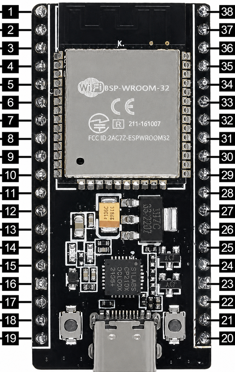
Pin Configuration and Descriptions

The ESP32 has a total of 38 pins (varies by module). Below is a summary of key pins:

Pin Name Function Description
GPIO0 General Purpose I/O Used for boot mode selection during startup.
GPIO2 General Purpose I/O Can be used as a standard GPIO pin.
GPIO12 General Purpose I/O Supports ADC, PWM, and other functions.
GPIO13 General Purpose I/O Supports ADC, PWM, and other functions.
GPIO15 General Purpose I/O Supports ADC, PWM, and other functions.
EN Enable Resets the chip when pulled low.
3V3 Power Supply Provides 3.3V output.
GND Ground Ground connection.
TX0 UART Transmit UART0 transmit pin for serial communication.
RX0 UART Receive UART0 receive pin for serial communication.

For a complete pinout, refer to the ESP32 datasheet provided by the manufacturer.

Usage Instructions

How to Use the ESP32 in a Circuit

  1. Power Supply: Connect the ESP32 to a stable 3.3V power source. Avoid exceeding the maximum voltage of 3.6V to prevent damage.
  2. Boot Mode: To upload code, connect GPIO0 to GND and reset the chip. After uploading, disconnect GPIO0 from GND.
  3. Programming: Use the Arduino IDE or ESP-IDF (Espressif IoT Development Framework) to program the ESP32. Install the necessary board definitions and libraries.
  4. Connections: Use the GPIO pins for interfacing with sensors, actuators, and other peripherals. Ensure proper voltage levels for connected devices.

Important Considerations

  • Voltage Levels: The ESP32 operates at 3.3V logic levels. Use level shifters if interfacing with 5V devices.
  • Power Consumption: Optimize power usage by utilizing sleep modes for battery-powered applications.
  • Antenna Placement: Ensure the onboard antenna has sufficient clearance from metal objects to avoid interference.

Example Code for Arduino UNO Integration

Below is an example of using the ESP32 to control an LED via Wi-Fi:

#include <WiFi.h> // Include the Wi-Fi library

const char* ssid = "Your_SSID";       // Replace with your Wi-Fi SSID
const char* password = "Your_Password"; // Replace with your Wi-Fi password

const int ledPin = 2; // GPIO2 is connected to the LED

void setup() {
  pinMode(ledPin, OUTPUT); // Set GPIO2 as an output pin
  Serial.begin(115200);    // Initialize serial communication

  // Connect to Wi-Fi
  Serial.print("Connecting to Wi-Fi");
  WiFi.begin(ssid, password);
  while (WiFi.status() != WL_CONNECTED) {
    delay(500);
    Serial.print(".");
  }
  Serial.println("\nWi-Fi connected!");
}

void loop() {
  digitalWrite(ledPin, HIGH); // Turn the LED on
  delay(1000);                // Wait for 1 second
  digitalWrite(ledPin, LOW);  // Turn the LED off
  delay(1000);                // Wait for 1 second
}

Notes:

  • Replace Your_SSID and Your_Password with your Wi-Fi credentials.
  • Ensure the ESP32 is connected to your computer via a USB cable for programming.

Troubleshooting and FAQs

Common Issues

  1. ESP32 Not Connecting to Wi-Fi

    • Ensure the SSID and password are correct.
    • Check if the Wi-Fi network is within range.
    • Verify that the router supports 2.4 GHz, as the ESP32 does not support 5 GHz.
  2. Code Upload Fails

    • Ensure GPIO0 is connected to GND during the upload process.
    • Check the USB cable and port for proper connection.
    • Install the correct USB-to-serial driver for your operating system.
  3. Random Resets or Instability

    • Verify that the power supply provides sufficient current (at least 500 mA).
    • Check for loose connections or short circuits.

Tips for Troubleshooting

  • Use the serial monitor to debug and view error messages.
  • Update the ESP32 board definitions and libraries in the Arduino IDE.
  • Test the ESP32 on a different computer or USB port to rule out hardware issues.

By following this documentation, you can effectively integrate and troubleshoot the ESP32 in your projects.