How to Use Ammeter: Examples, Pinouts, and Specs
Ammeter Documentation
1. Introduction
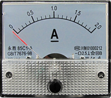
An ammeter is an electronic instrument designed to measure the current flowing through a circuit. The current is typically expressed in amperes (A). To ensure accurate readings, an ammeter is connected in series with the circuit, allowing the entire current to pass through the device. Ammeters are essential tools in electronics for monitoring and troubleshooting circuits, as well as for ensuring that components operate within their specified current limits.
Common Applications and Use Cases:
- Electronics Testing and Debugging: Measuring current in prototype circuits.
- Battery Monitoring: Checking the current draw of devices powered by batteries.
- Power Supply Testing: Verifying the current output of power supplies.
- Industrial Applications: Monitoring current in motors, generators, and other equipment.
- Educational Use: Teaching basic electrical principles in labs and classrooms.
2. Technical Specifications
Below are the general technical specifications for a typical ammeter. Note that specific models may vary, so always refer to the datasheet of the particular ammeter you are using.
Key Technical Details
| Parameter | Specification |
|---|---|
| Measurement Range | 0–10 A (typical), varies by model |
| Accuracy | ±1% of full scale (typical) |
| Input Impedance | Very low (to minimize voltage drop) |
| Operating Voltage | 0–30 V (depends on the circuit) |
| Display Type | Analog (needle) or Digital (LCD/LED) |
| Power Supply (if digital) | 5 V or 9 V (for digital ammeters) |
| Shunt Resistor | Internal or external (varies by model) |
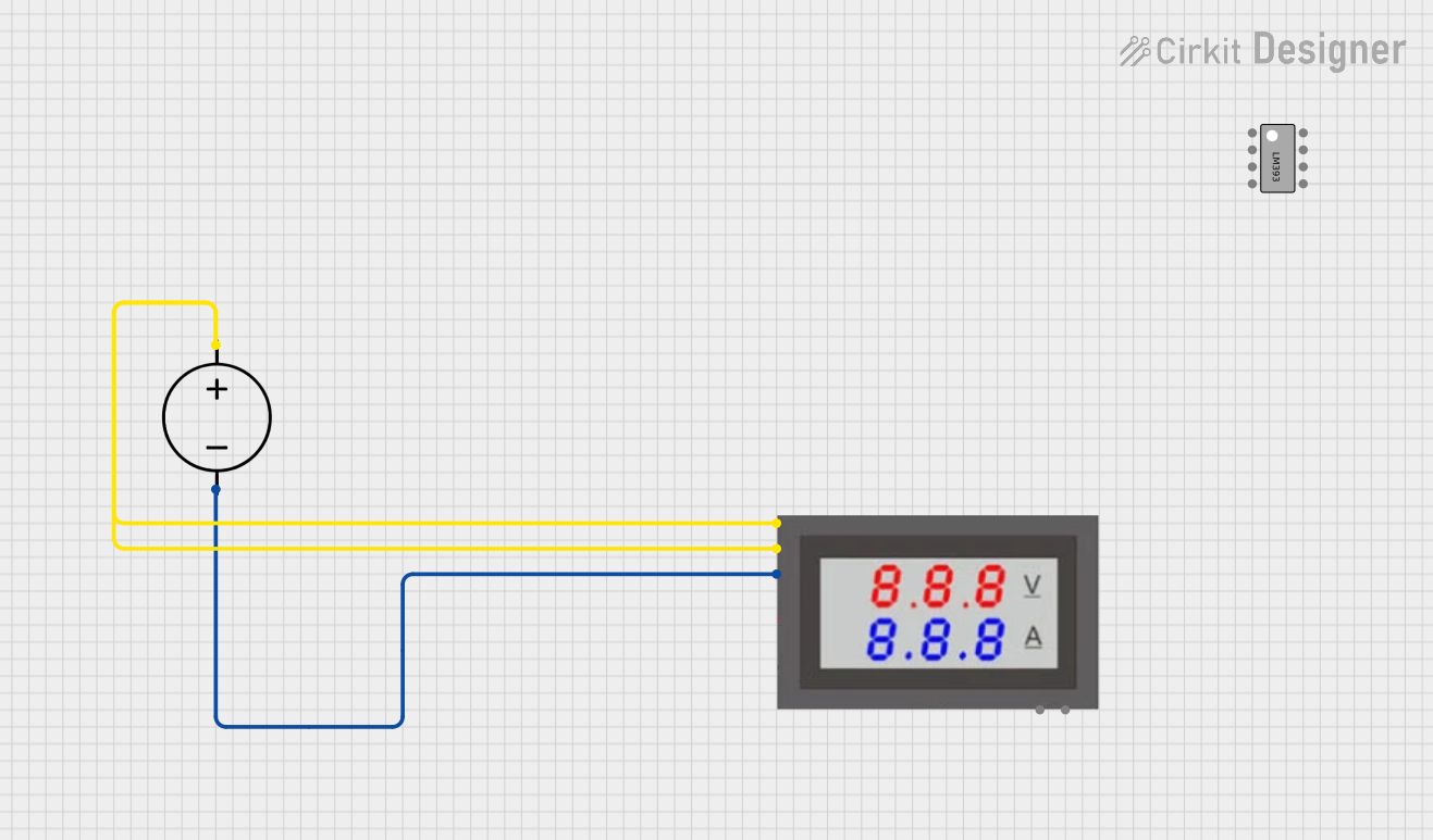
Pin Configuration and Descriptions (for Digital Ammeters)
| Pin Name | Description |
|---|---|
| VCC | Power supply input (e.g., 5 V or 9 V for digital models) |
| GND | Ground connection |
| IN+ | Positive input terminal for current measurement |
| IN- | Negative input terminal for current measurement |
3. Usage Instructions
How to Use an Ammeter in a Circuit
- Turn Off the Circuit: Before connecting the ammeter, ensure the circuit is powered off to avoid damage or incorrect readings.
- Break the Circuit: Identify the point in the circuit where you want to measure the current. Open the circuit at this point.
- Connect the Ammeter in Series:
- Connect the positive terminal of the ammeter (IN+) to the positive side of the circuit.
- Connect the negative terminal of the ammeter (IN-) to the load or the next component in the circuit.
- Power On the Circuit: Turn on the circuit and observe the current reading on the ammeter display.
- Record the Reading: Note the current value for your analysis or troubleshooting.
Important Considerations and Best Practices
- Series Connection: Always connect the ammeter in series with the circuit. Connecting it in parallel can damage the ammeter or the circuit.
- Current Range: Ensure the ammeter's range is suitable for the expected current. If unsure, start with the highest range and work downward.
- Shunt Resistor: Some ammeters require an external shunt resistor for high-current measurements. Follow the manufacturer's instructions for proper shunt placement.
- Polarity: Observe the correct polarity when connecting the ammeter to avoid incorrect readings or damage.
- Voltage Drop: Be aware that the ammeter introduces a small voltage drop in the circuit due to its internal resistance. This is usually negligible but may affect sensitive circuits.
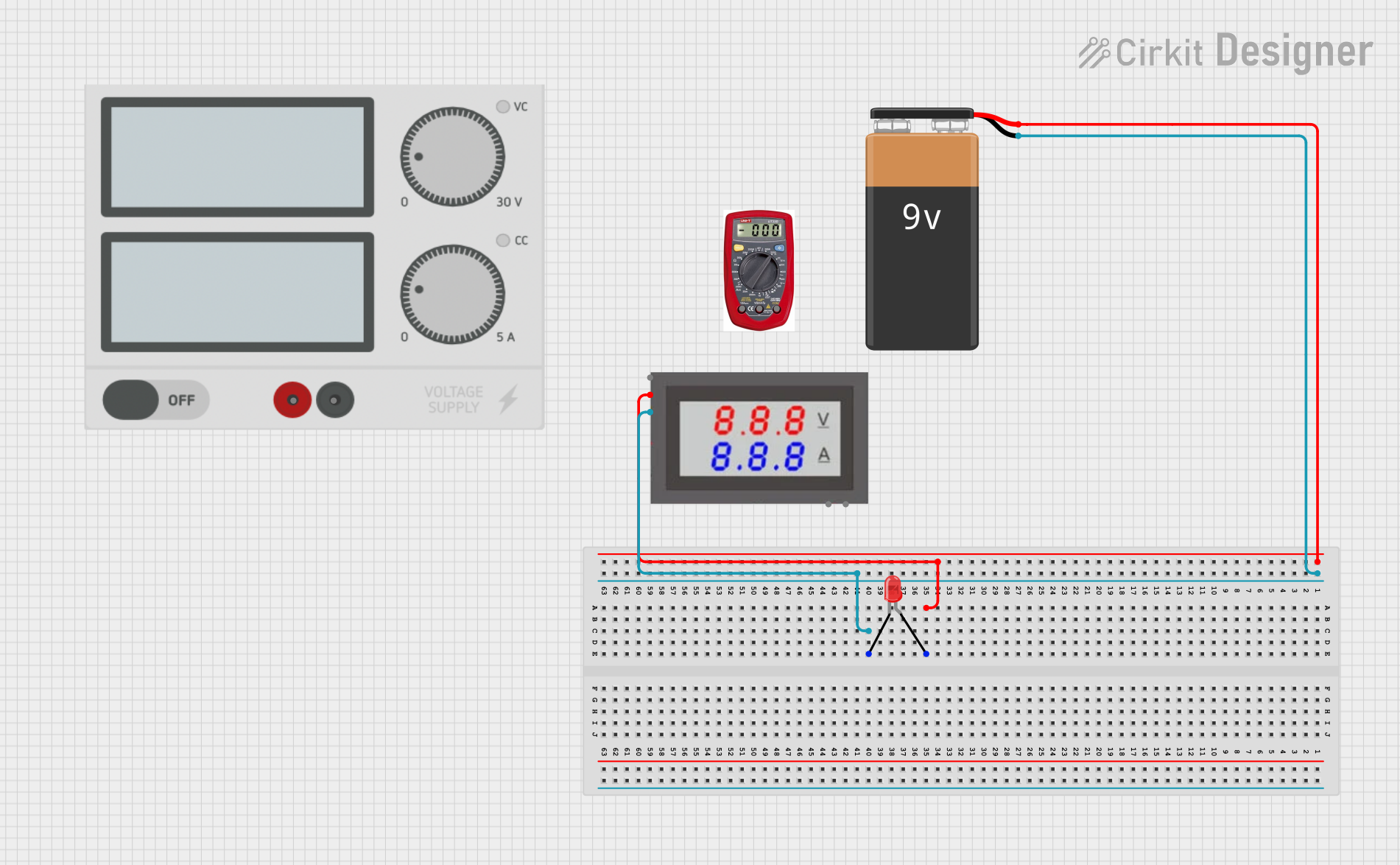
4. Example: Using a Digital Ammeter with Arduino UNO
A digital ammeter can be used to measure the current drawn by a load connected to an Arduino UNO. Below is an example setup and code to demonstrate this.
Circuit Diagram
- Connect the ammeter in series with the load (e.g., an LED and resistor) connected to the Arduino UNO.
- Ensure the ammeter's positive terminal (IN+) is connected to the Arduino's output pin, and the negative terminal (IN-) is connected to the load.
Arduino Code Example
/*
  Example: Measuring Current with a Digital Ammeter
  This code demonstrates how to control an LED connected to an Arduino UNO
  while measuring the current using a digital ammeter.
*/

const int ledPin = 9; // Pin connected to the LED

void setup() {
  pinMode(ledPin, OUTPUT); // Set the LED pin as an output
}

void loop() {
  digitalWrite(ledPin, HIGH); // Turn the LED on
  delay(1000);               // Wait for 1 second
  digitalWrite(ledPin, LOW);  // Turn the LED off
  delay(1000);               // Wait for 1 second
}
Steps:
- Connect the LED and a suitable resistor (e.g., 220 Ω) to the Arduino's
ledPin(pin 9). - Insert the ammeter in series with the LED to measure the current.
- Upload the code to the Arduino UNO.
- Observe the current reading on the ammeter as the LED turns on and off.
5. Troubleshooting and FAQs
Common Issues and Solutions
| Issue | Possible Cause | Solution |
|---|---|---|
| Ammeter shows no reading | Circuit not properly connected in series | Verify the series connection of the ammeter. |
| Ammeter displays negative current | Polarity is reversed | Swap the IN+ and IN- connections. |
| Ammeter is damaged or not working | Connected in parallel instead of series | Replace the ammeter and ensure proper series connection. |
| Reading fluctuates or is unstable | Poor connections or noisy circuit | Check all connections and use proper shielding. |
| Current exceeds ammeter's range | Overload condition | Use a higher-range ammeter or external shunt resistor. |
Frequently Asked Questions (FAQs)
Can I use an ammeter to measure AC current?
- Only if the ammeter is designed for AC measurements. Most basic ammeters are for DC only.
What happens if I connect the ammeter in parallel?
- This can cause a short circuit, potentially damaging the ammeter and the circuit.
How do I measure very high currents?
- Use an external shunt resistor rated for the expected current. Connect the ammeter across the shunt to measure the voltage drop, which can be converted to current.
Why does the ammeter introduce a voltage drop?
- The ammeter has a small internal resistance, which causes a slight voltage drop. This is usually negligible in most circuits.
By following this documentation, users can effectively integrate an ammeter into their circuits for accurate current measurements. Always refer to the specific ammeter's datasheet for additional details and safety precautions.
Explore Projects Built with Ammeter
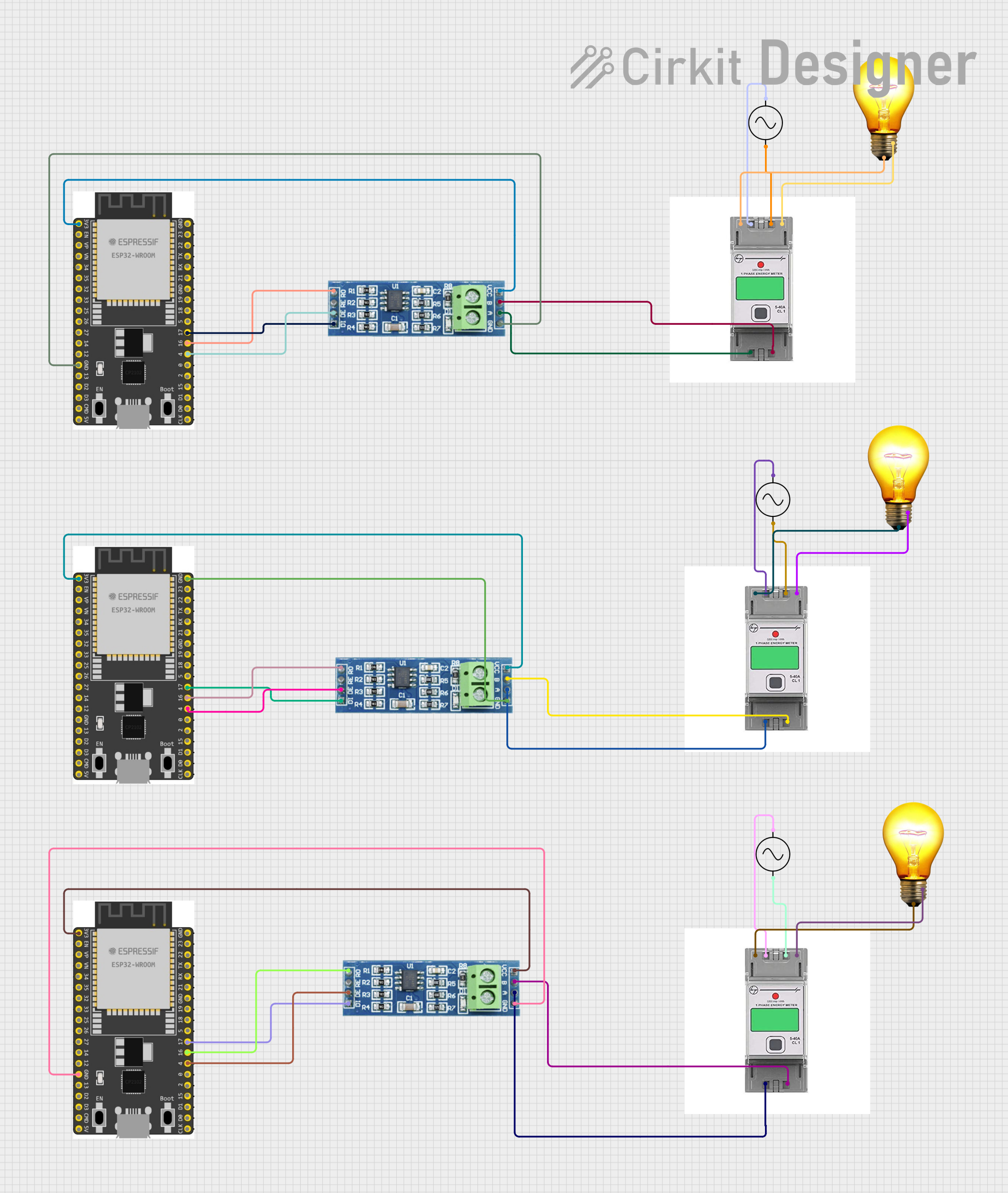
Explore Projects Built with Ammeter