How to Use MKE-S02 LDR Light Sensor: Examples, Pinouts, and Specs
Introduction
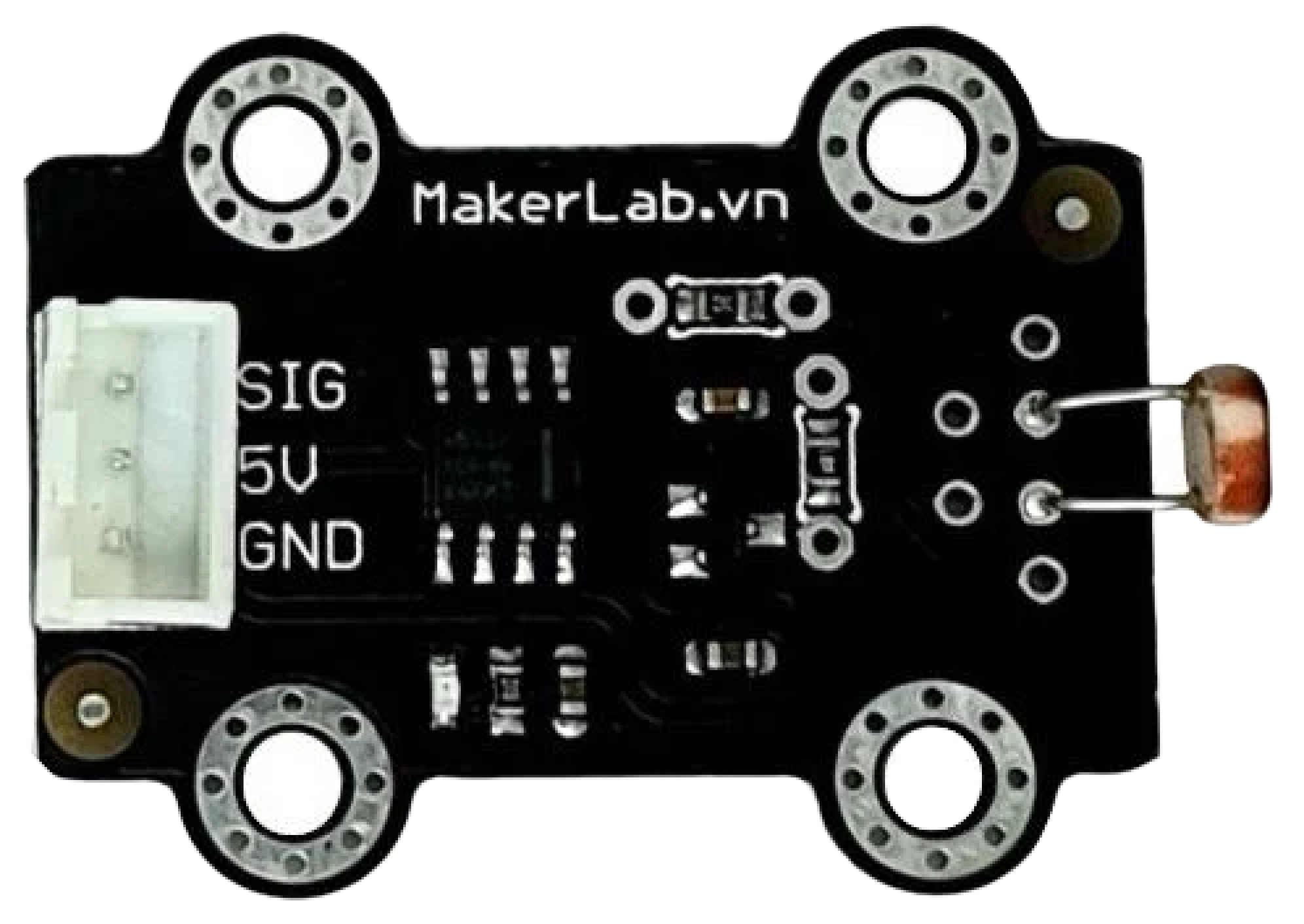
The MKE-S02 LDR Light Sensor is a photoresistor, also known as a light-dependent resistor (LDR), which is a passive electronic component whose resistance varies with the intensity of light it is exposed to. This characteristic makes it ideal for creating light-sensitive circuits, which can be used in a variety of applications such as automatic lighting control, alarm systems, and environmental light monitoring.
Explore Projects Built with MKE-S02 LDR Light Sensor

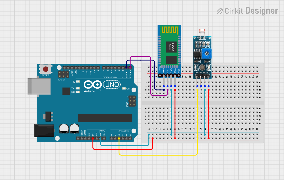

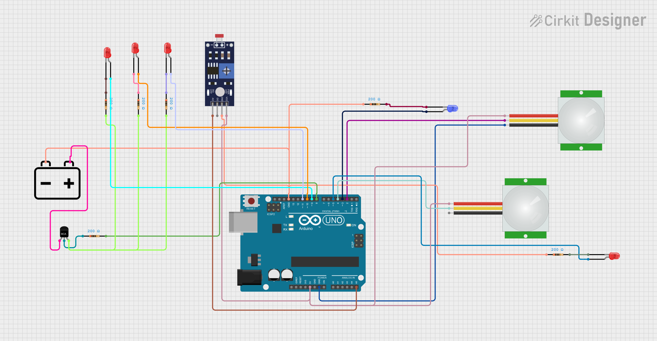
Explore Projects Built with MKE-S02 LDR Light Sensor
Common Applications and Use Cases
- Automatic night lights
- Security systems with light-based triggering
- Light intensity monitoring for agricultural applications
- Automatic street lighting
- Light-activated switches for consumer electronics
Technical Specifications
The MKE-S02 LDR Light Sensor has the following key technical specifications:
| Parameter | Specification |
|---|---|
| Resistance (Dark) | 1 MΩ (Typical) |
| Resistance (Light) | 10 kΩ (Typical) |
| Power Rating | 150 mW |
| Maximum Voltage | 150 V (Peak) |
| Spectral Peak | 540 nm |
| Operating Temp. | -30°C to +70°C |
Pin Configuration and Descriptions
The MKE-S02 LDR Light Sensor is a two-terminal device:
| Pin | Description |
|---|---|
| 1 | LDR Sensor (Anode) |
| 2 | LDR Sensor (Cathode) |
Usage Instructions
How to Use the Component in a Circuit
- Connecting the LDR: Connect one terminal of the LDR to a voltage source (Vcc) and the other terminal to an analog input pin of a microcontroller through a fixed resistor to form a voltage divider.
- Choosing a Resistor: Select a fixed resistor value that is close to the resistance of the LDR at the light level you wish to detect.
- Reading Values: Use the microcontroller's ADC (Analog-to-Digital Converter) to read the voltage across the fixed resistor, which varies with light intensity.
Important Considerations and Best Practices
- Avoid exposing the LDR to extreme light intensities that could exceed its maximum voltage rating.
- Shield the sensor from artificial light sources when calibrating for natural light detection to prevent false readings.
- Use a capacitor in parallel with the LDR to smooth out rapid changes in light and to reduce noise in the ADC readings.
Example Circuit and Arduino Code
The following example demonstrates how to connect the MKE-S02 LDR Light Sensor to an Arduino UNO and read light levels.
Circuit Diagram
Vcc (5V) --- LDR ---+--- Resistor (10kΩ) --- GND
                     |
                 Analog Pin A0
Arduino Sketch
// Define the LDR pin
const int ldrPin = A0;

void setup() {
  // Initialize serial communication
  Serial.begin(9600);
}

void loop() {
  // Read the value from the LDR
  int ldrValue = analogRead(ldrPin);

  // Convert the analog reading to a voltage
  float voltage = ldrValue * (5.0 / 1023.0);

  // Print out the value in the Serial Monitor
  Serial.print("LDR Value: ");
  Serial.print(ldrValue);
  Serial.print(" - Voltage: ");
  Serial.println(voltage);

  // Wait for a bit before reading again
  delay(500);
}
Troubleshooting and FAQs
Common Issues
- Inconsistent Readings: Ensure that there are no loose connections and that the LDR is not exposed to intermittent light sources.
- No Change in Readings: Verify that the LDR is not damaged and that it is correctly connected in the voltage divider circuit.
Solutions and Tips for Troubleshooting
- If readings are erratic, add a capacitor in parallel with the LDR to stabilize the readings.
- Ensure that the fixed resistor value is appropriate for the expected range of light levels.
- Calibrate your sensor by mapping the ADC readings to known light levels under controlled conditions.
FAQs
Q: Can I use the MKE-S02 LDR Light Sensor with a 3.3V system?
A: Yes, the sensor can be used with a 3.3V system, but the voltage divider and ADC calculations will need to be adjusted accordingly.
Q: How do I calibrate the sensor for accurate light measurements?
A: Use a known light source and measure the resistance of the LDR under that condition. Then, compare the ADC readings to the expected values and adjust your code accordingly.
Q: What is the lifespan of the MKE-S02 LDR Light Sensor?
A: The lifespan can vary based on usage, but LDRs typically have a long operational life if used within their specified ratings. Avoid exposure to high-intensity light to prevent premature aging.