How to Use Sigle Dot Led Matrix: Examples, Pinouts, and Specs
Introduction
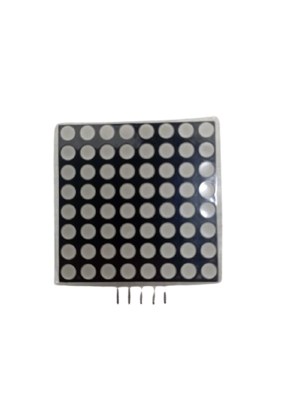
The Single Dot LED Matrix is a compact display module consisting of a grid of LEDs that can be individually controlled to create patterns or display information. This versatile component is widely used in applications such as digital signage, decorative lighting, and simple visual displays. Its ability to illuminate specific LEDs in a grid makes it ideal for creating custom animations, scrolling text, or visual indicators in embedded systems.
Common applications include:
- Digital signage and message boards
- Decorative lighting and art installations
- Educational projects and prototyping
- Visual indicators in embedded systems
- Simple gaming displays (e.g., Tetris or Snake)
Explore Projects Built with Sigle Dot Led Matrix
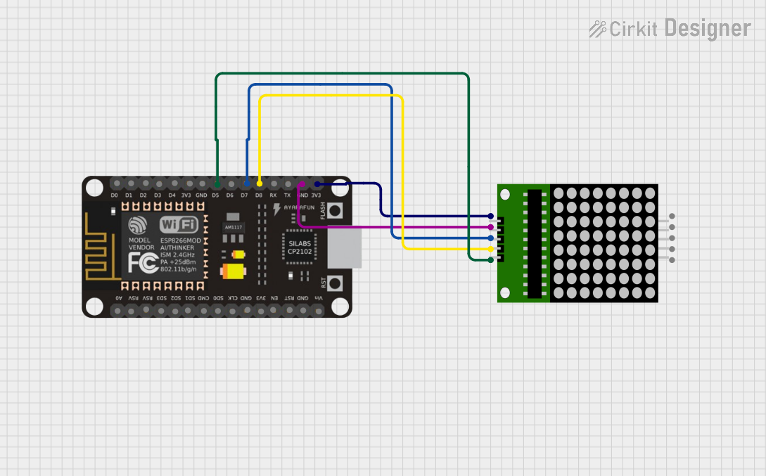
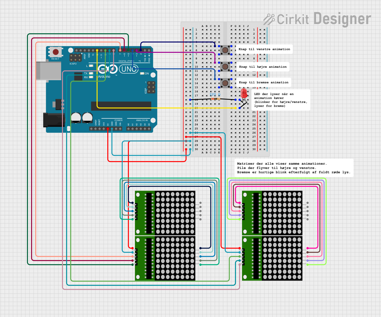
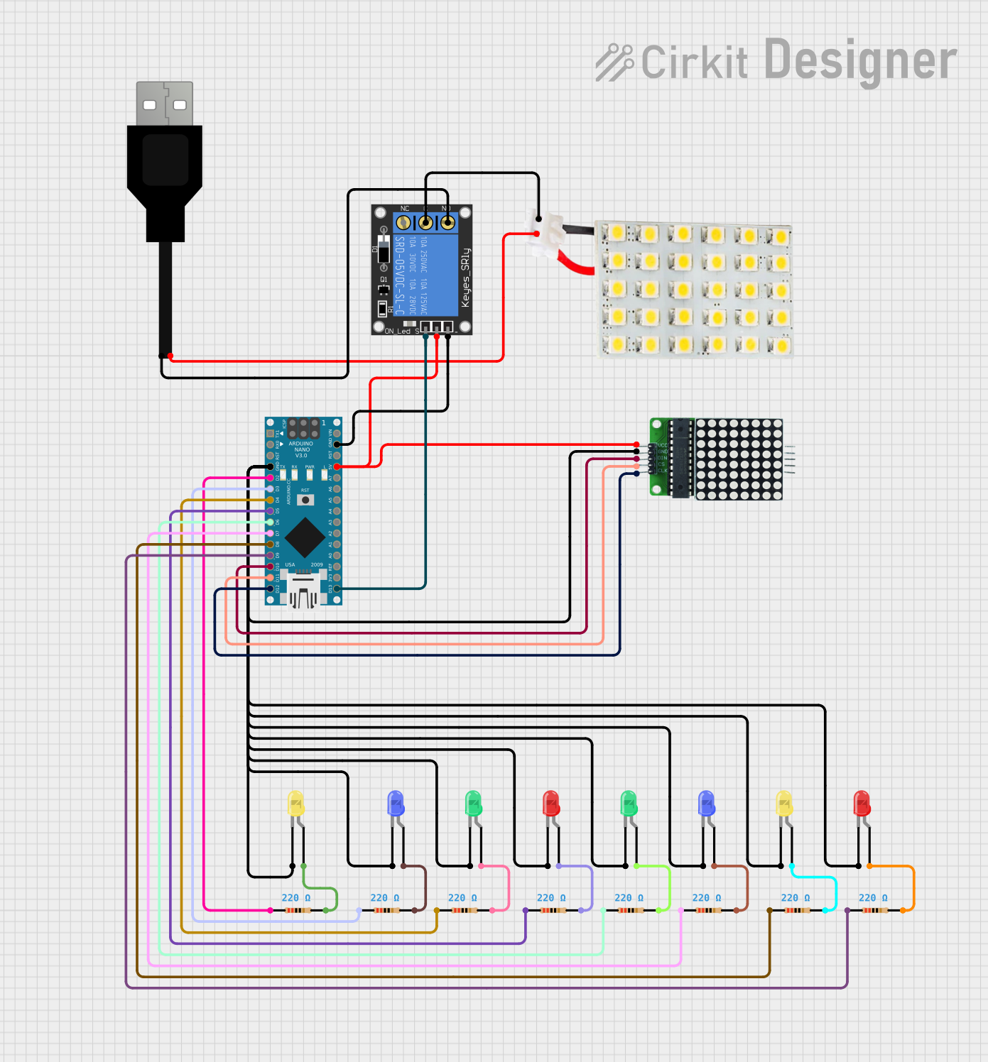

Explore Projects Built with Sigle Dot Led Matrix
Technical Specifications
The Single Dot LED Matrix is available in various configurations, such as 8x8, 5x7, or 4x4 grids. Below are the general technical specifications for an 8x8 LED matrix:
| Parameter | Specification |
|---|---|
| Operating Voltage | 3.3V to 5V |
| Operating Current | 20mA per LED (typical) |
| LED Color | Red, Green, Blue, or Multicolor |
| Matrix Configuration | Common Cathode or Common Anode |
| Dimensions | 32mm x 32mm (for 8x8 matrix) |
| Pin Count | 16 pins (8 rows + 8 columns) |
Pin Configuration
The pinout of the Single Dot LED Matrix depends on its configuration (common cathode or common anode). Below is the pin configuration for a standard 8x8 common cathode matrix:
| Pin Number | Description |
|---|---|
| 1 | Column 1 (C1) |
| 2 | Column 2 (C2) |
| 3 | Column 3 (C3) |
| 4 | Column 4 (C4) |
| 5 | Column 5 (C5) |
| 6 | Column 6 (C6) |
| 7 | Column 7 (C7) |
| 8 | Column 8 (C8) |
| 9 | Row 8 (R8) |
| 10 | Row 7 (R7) |
| 11 | Row 6 (R6) |
| 12 | Row 5 (R5) |
| 13 | Row 4 (R4) |
| 14 | Row 3 (R3) |
| 15 | Row 2 (R2) |
| 16 | Row 1 (R1) |
Usage Instructions
How to Use the Component in a Circuit
- Connect the Matrix to a Microcontroller: Use a microcontroller (e.g., Arduino UNO) to control the rows and columns of the matrix. Each LED is activated by driving the corresponding row and column pins.
- Use Current-Limiting Resistors: To prevent damage to the LEDs, connect a resistor (typically 220Ω to 1kΩ) in series with each column or row pin.
- Multiplexing: Since controlling all LEDs simultaneously requires many pins, use multiplexing to light up one row or column at a time in rapid succession. This creates the illusion of all LEDs being lit simultaneously.
- Driver ICs: For larger matrices, consider using driver ICs like the MAX7219 to simplify control and reduce the number of required microcontroller pins.
Example Circuit with Arduino UNO
Below is an example of how to connect an 8x8 LED matrix to an Arduino UNO using current-limiting resistors:
- Connect the row pins (R1 to R8) to digital pins 2 to 9 on the Arduino.
- Connect the column pins (C1 to C8) to digital pins 10 to 13 and A0 to A3.
- Place a 220Ω resistor in series with each column pin.
Example Arduino Code
The following code demonstrates how to light up a single LED in the matrix:
// Define row and column pins
const int rowPins[8] = {2, 3, 4, 5, 6, 7, 8, 9};
const int colPins[8] = {10, 11, 12, 13, A0, A1, A2, A3};

void setup() {
  // Set all row and column pins as outputs
  for (int i = 0; i < 8; i++) {
    pinMode(rowPins[i], OUTPUT);
    pinMode(colPins[i], OUTPUT);
  }
}

void loop() {
  // Light up the LED at Row 1, Column 1
  digitalWrite(rowPins[0], LOW);  // Activate Row 1 (common cathode)
  digitalWrite(colPins[0], HIGH); // Activate Column 1
  delay(1000);                    // Keep the LED on for 1 second

  // Turn off the LED
  digitalWrite(rowPins[0], HIGH); // Deactivate Row 1
  digitalWrite(colPins[0], LOW);  // Deactivate Column 1
  delay(1000);                    // Wait for 1 second
}
Important Considerations and Best Practices
- Power Supply: Ensure the power supply can handle the total current draw of the matrix.
- Heat Management: Avoid driving all LEDs at full brightness for extended periods to prevent overheating.
- Refresh Rate: Use a refresh rate of at least 60Hz for smooth animations and to avoid flickering.
- Driver ICs: For larger matrices or complex patterns, use a driver IC like the MAX7219 to simplify wiring and control.
Troubleshooting and FAQs
Common Issues and Solutions
Some LEDs Do Not Light Up:
- Check the connections for loose wires or incorrect pin mapping.
- Verify that the corresponding row and column pins are being activated.
Entire Matrix Does Not Work:
- Ensure the power supply is connected and providing the correct voltage.
- Check for proper grounding of the matrix and microcontroller.
Flickering LEDs:
- Increase the refresh rate in your code.
- Verify that the power supply can handle the current draw.
Dim LEDs:
- Reduce the value of the current-limiting resistors (e.g., use 220Ω instead of 1kΩ).
- Ensure the microcontroller pins are sourcing enough current.
FAQs
Q: Can I use a Single Dot LED Matrix with a Raspberry Pi?
A: Yes, you can use a Raspberry Pi to control the matrix. However, due to the limited GPIO pins, you may need a driver IC like the MAX7219 or a shift register.
Q: How do I display scrolling text on the matrix?
A: Use a library like the "LedControl" library for Arduino, which simplifies controlling the matrix and includes functions for scrolling text.
Q: Can I chain multiple matrices together?
A: Yes, you can chain multiple matrices using driver ICs like the MAX7219. This allows you to create larger displays with minimal wiring.
By following this documentation, you can effectively use the Single Dot LED Matrix in your projects and troubleshoot common issues with ease.