How to Use ir: Examples, Pinouts, and Specs
Introduction
Infrared (IR) components are electronic devices designed to transmit and receive infrared light, which is invisible to the human eye but falls within the electromagnetic spectrum. These components are widely used in applications such as remote controls, proximity sensors, object detection, and wireless communication systems. IR components are essential in enabling devices to interact wirelessly over short distances.
Common applications include:
- Remote controls for TVs, air conditioners, and other appliances
- IR obstacle detection in robotics
- Data transmission between devices
- Motion detection and security systems
Explore Projects Built with ir
Explore Projects Built with ir
Technical Specifications
General Specifications
| Parameter | Value/Range |
|---|---|
| Wavelength Range | 700 nm to 1 mm (Infrared spectrum) |
| Operating Voltage | 2V to 5V (varies by component type) |
| Current Consumption | 10 mA to 50 mA (typical) |
| Communication Protocols | Modulated signals (e.g., 38 kHz) |
| Transmission Range | Up to 10 meters (depending on power) |
Pin Configuration and Descriptions
IR Transmitter (LED)
| Pin Number | Name | Description |
|---|---|---|
| 1 | Anode (+) | Connect to the positive terminal of the power supply. |
| 2 | Cathode (-) | Connect to ground (GND). |
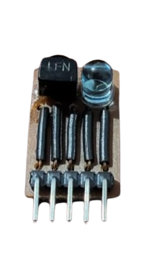
IR Receiver (Photodiode/Phototransistor)
| Pin Number | Name | Description |
|---|---|---|
| 1 | VCC | Connect to the positive terminal of the power supply. |
| 2 | GND | Connect to ground (GND). |
| 3 | OUT | Outputs the detected signal (digital or analog). |
Usage Instructions
Using an IR Transmitter and Receiver in a Circuit
Connect the IR Transmitter:
- Connect the anode of the IR LED to a current-limiting resistor (typically 220Ω to 1kΩ).
- Connect the other end of the resistor to a GPIO pin of a microcontroller or a power source.
- Connect the cathode to ground.
Connect the IR Receiver:
- Connect the VCC pin of the receiver to a 5V power supply.
- Connect the GND pin to ground.
- Connect the OUT pin to a GPIO pin of a microcontroller or to an external circuit for signal processing.
Test the Circuit:
- Use an oscilloscope or multimeter to verify the output signal from the receiver.
- Ensure the transmitter and receiver are aligned for proper communication.
Important Considerations
- Modulation Frequency: Most IR receivers are designed to detect signals modulated at a specific frequency (e.g., 38 kHz). Ensure the transmitter matches this frequency.
- Ambient Light Interference: IR components can be affected by sunlight or other strong light sources. Use modulation to reduce interference.
- Alignment: Ensure the transmitter and receiver are properly aligned for optimal performance.
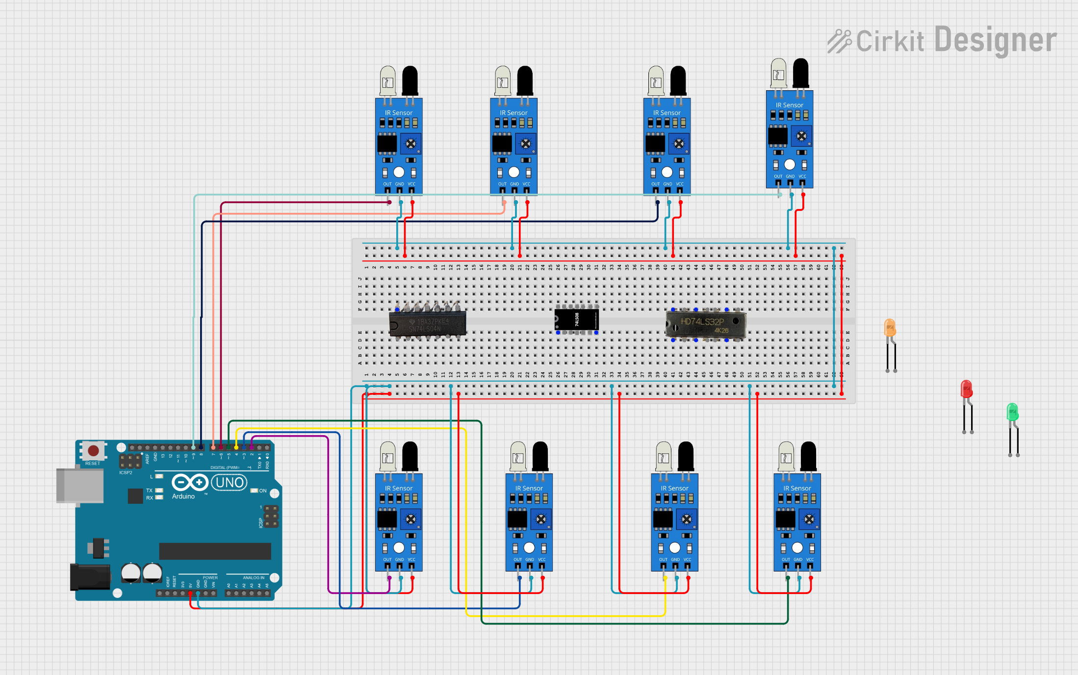
Example: Using IR Components with Arduino UNO
Below is an example of how to use an IR transmitter and receiver with an Arduino UNO to detect an obstacle.
Circuit Connections
- Connect the IR LED anode to Arduino pin 3 through a 220Ω resistor.
- Connect the IR LED cathode to GND.
- Connect the IR receiver VCC to 5V, GND to GND, and OUT to Arduino pin 2.
Arduino Code
#include <IRremote.h> // Include the IRremote library

int receiverPin = 2; // Pin connected to the IR receiver OUT pin
int ledPin = 13;     // Built-in LED for visual feedback

IRrecv irrecv(receiverPin); // Create an IR receiver object
decode_results results;     // Variable to store decoded IR signals

void setup() {
  pinMode(ledPin, OUTPUT);  // Set LED pin as output
  Serial.begin(9600);       // Initialize serial communication
  irrecv.enableIRIn();      // Start the IR receiver
}

void loop() {
  if (irrecv.decode(&results)) { // Check if an IR signal is received
    Serial.println("IR signal detected!"); // Print message to serial monitor
    digitalWrite(ledPin, HIGH);  // Turn on LED
    delay(500);                  // Wait for 500ms
    digitalWrite(ledPin, LOW);   // Turn off LED
    irrecv.resume();             // Prepare to receive the next signal
  }
}
Notes:
- Install the
IRremotelibrary in the Arduino IDE before uploading the code. - Ensure the IR transmitter and receiver are aligned and within range.
Troubleshooting and FAQs
Common Issues
No Signal Detected:
- Ensure the transmitter and receiver are properly aligned.
- Verify the transmitter is emitting IR light using a smartphone camera (IR light is visible on most cameras).
Interference from Ambient Light:
- Use a modulated IR signal to reduce interference.
- Avoid direct sunlight or strong artificial light near the components.
Short Range:
- Check the power supply to the IR LED.
- Use a lower value resistor to increase the current through the IR LED (within safe limits).
Receiver Not Responding:
- Verify the receiver's operating frequency matches the transmitter's modulation frequency.
- Check all connections and ensure the receiver is powered correctly.
FAQs
Q: Can I use IR components for long-distance communication?
A: IR components are typically designed for short-range communication (up to 10 meters). For longer distances, consider using RF or other wireless technologies.
Q: How do I know if my IR LED is working?
A: Point the IR LED at a smartphone camera. If it is functioning, you will see a faint light on the camera screen.
Q: Can I use multiple IR receivers in the same circuit?
A: Yes, but ensure they are spaced apart to avoid interference and use unique modulation frequencies if needed.
Q: What is the typical lifespan of an IR LED?
A: IR LEDs have a long lifespan, typically exceeding 50,000 hours under normal operating conditions.