How to Use OPA547_eval: Examples, Pinouts, and Specs
Introduction
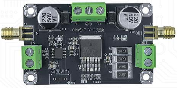
The OPA547_eval is an evaluation board designed by Texas Instruments for the OPA547 operational amplifier. The OPA547 is a high-performance, high-voltage, and high-current operational amplifier, making it suitable for a wide range of applications. The evaluation board simplifies the process of testing and evaluating the OPA547, providing a convenient platform to explore its features and capabilities.
Explore Projects Built with OPA547_eval

Explore Projects Built with OPA547_eval
Common Applications and Use Cases
- Motor control and drive circuits
- Power supply regulation
- Signal conditioning in industrial systems
- Audio amplification
- Test and measurement equipment
The OPA547_eval is ideal for engineers and designers who want to prototype and validate their designs using the OPA547 op-amp.
Technical Specifications
Key Technical Details
- Operational Amplifier: OPA547
- Supply Voltage Range: ±10V to ±30V (dual supply) or 20V to 60V (single supply)
- Output Current: Up to 500mA (adjustable current limit)
- Slew Rate: 0.8V/µs
- Gain Bandwidth Product: 1MHz
- Input Offset Voltage: 2mV (typical)
- Thermal Protection: Built-in thermal shutdown
- Board Dimensions: Compact PCB layout for easy integration
Pin Configuration and Descriptions
The OPA547_eval board provides access to the key pins of the OPA547 op-amp. Below is the pin configuration:
| Pin Name | Description |
|---|---|
| V+ | Positive power supply input (connect to +Vcc). |
| V- | Negative power supply input (connect to -Vcc or ground for single supply). |
| In+ | Non-inverting input of the op-amp. |
| In- | Inverting input of the op-amp. |
| Out | Output of the op-amp. |
| ILIM | Current limit adjustment pin (connect a resistor to set the current limit). |
| NC | No connection (reserved for internal use). |
| GND | Ground connection for the evaluation board. |
Usage Instructions
How to Use the OPA547_eval in a Circuit
Power Supply Setup:
- Connect a dual power supply (e.g., ±15V) or a single power supply (e.g., 30V) to the V+ and V- pins.
- Ensure the power supply voltage is within the specified range (±10V to ±30V or 20V to 60V).
Input Signal:
- Connect the input signal to the In+ and/or In- pins, depending on the desired configuration (non-inverting or inverting).
Output Connection:
- Connect the load to the Out pin. Ensure the load does not exceed the maximum output current of 500mA.
Current Limit Adjustment:
- Use a resistor between the ILIM pin and ground to set the desired current limit. Refer to the OPA547 datasheet for the resistor value calculation.
Thermal Considerations:
- Ensure proper heat dissipation by mounting the evaluation board on a heatsink or using forced air cooling if operating at high currents.
Important Considerations and Best Practices
- Bypass Capacitors: Place decoupling capacitors (e.g., 0.1µF and 10µF) close to the V+ and V- pins to ensure stable operation.
- Thermal Shutdown: The OPA547 includes thermal protection. If the device overheats, it will shut down to prevent damage. Ensure adequate cooling to avoid frequent shutdowns.
- Current Limit: Always set the current limit appropriately to protect the op-amp and the connected load.
- PCB Layout: Minimize trace lengths for high-current paths to reduce resistance and inductance.
Example Code for Arduino UNO
The OPA547_eval can be used with an Arduino UNO for basic signal generation and control. Below is an example of generating a PWM signal to drive the OPA547:
// Example: Generating a PWM signal to control the OPA547 output
// Connect the Arduino PWM pin (e.g., D9) to the In+ pin of the OPA547_eval

const int pwmPin = 9; // PWM output pin

void setup() {
  pinMode(pwmPin, OUTPUT); // Set the PWM pin as output
}

void loop() {
  // Generate a PWM signal with varying duty cycle
  for (int dutyCycle = 0; dutyCycle <= 255; dutyCycle++) {
    analogWrite(pwmPin, dutyCycle); // Set PWM duty cycle (0-255)
    delay(10); // Wait for 10ms
  }
  for (int dutyCycle = 255; dutyCycle >= 0; dutyCycle--) {
    analogWrite(pwmPin, dutyCycle); // Decrease PWM duty cycle
    delay(10); // Wait for 10ms
  }
}
Note: The PWM signal can be filtered using an RC low-pass filter to create an analog voltage for the OPA547 input.
Troubleshooting and FAQs
Common Issues and Solutions
No Output Signal:
- Cause: Incorrect power supply connection.
- Solution: Verify the power supply connections and ensure the voltage is within the specified range.
Thermal Shutdown:
- Cause: Excessive current or inadequate cooling.
- Solution: Reduce the load current or improve heat dissipation using a heatsink or fan.
Unstable Output:
- Cause: Insufficient bypass capacitors or poor PCB layout.
- Solution: Add decoupling capacitors close to the power supply pins and minimize trace lengths.
Current Limit Not Working:
- Cause: Incorrect resistor value on the ILIM pin.
- Solution: Recalculate and replace the resistor based on the desired current limit.
FAQs
Q1: Can the OPA547_eval be used with a single power supply?
A1: Yes, the OPA547_eval supports single-supply operation. Connect the V- pin to ground and ensure the supply voltage is between 20V and 60V.
Q2: How do I calculate the current limit resistor value?
A2: Use the formula provided in the OPA547 datasheet:
[ R_{ILIM} = \frac{0.7}{I_{LIMIT}} ]
where ( I_{LIMIT} ) is the desired current limit in amperes.
Q3: What is the maximum load the OPA547 can drive?
A3: The OPA547 can drive loads up to 500mA. Ensure the load impedance and current do not exceed this limit.
Q4: Can I use the OPA547_eval for audio applications?
A4: Yes, the OPA547 is suitable for audio amplification, especially in high-power applications.
This documentation provides a comprehensive guide to using the OPA547_eval evaluation board. For further details, refer to the official Texas Instruments datasheet and application notes.