Cirkit Designer Logo
Cirkit Designer
Your all-in-one circuit design IDE
Home / 
Component Documentation

How to Use HC-SR501 PIR motion sensor: Examples, Pinouts, and Specs

Image of HC-SR501 PIR motion sensor
Cirkit Designer LogoDesign with HC-SR501 PIR motion sensor in Cirkit Designer

Introduction

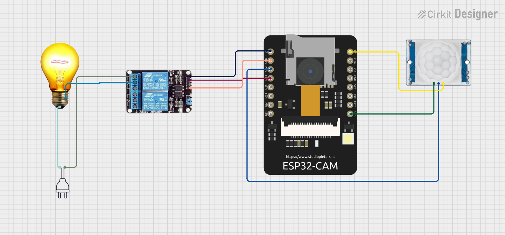
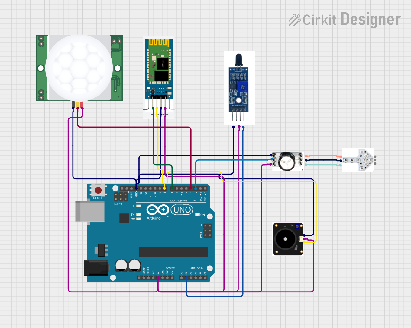
The HC-SR501 PIR (Passive Infrared) motion sensor is a versatile and low-cost sensor that detects motion based on the infrared radiation emitted by objects in its field of view. It is widely used in various applications such as security systems, lighting control, and home automation projects. The sensor is designed to be easily integrated into circuits and can be used with microcontrollers like the Arduino UNO.

Explore Projects Built with HC-SR501 PIR motion sensor

Use Cirkit Designer to design, explore, and prototype these projects online. Some projects support real-time simulation. Click "Open Project" to start designing instantly!
PIR Motion-Activated LED Light
Image of 0: A project utilizing HC-SR501 PIR motion sensor in a practical application
This circuit is a simple motion-activated LED light system. The HC-SR505 Mini PIR Motion Sensing Module is powered by a 9V battery and detects motion, upon which it sends an output signal to turn on the red LED. The LED and the PIR sensor share a common ground with the battery, completing the circuit.
Cirkit Designer LogoOpen Project in Cirkit Designer
Raspberry Pi 5 Motion Detection System with HC-SR501 Sensor
Image of PIR: A project utilizing HC-SR501 PIR motion sensor in a practical application
This circuit connects a Raspberry Pi 5 to an HC-SR501 motion sensor. The Raspberry Pi provides power to the motion sensor and reads its output signal through GPIO 17, allowing the Raspberry Pi to detect motion events.
Cirkit Designer LogoOpen Project in Cirkit Designer
ESP32 CAM-Based Wi-Fi Motion-Activated Smart Light
Image of ESP32 CAM: A project utilizing HC-SR501 PIR motion sensor in a practical application
This circuit features an ESP32 CAM microcontroller connected to an HC-SR501 PIR motion sensor and a 2-channel relay module. The PIR sensor output is connected to a GPIO pin on the ESP32, allowing it to detect motion and signal the microcontroller. The ESP32 controls the relay, which in turn switches an AC bulb on or off, effectively creating a motion-activated light system.
Cirkit Designer LogoOpen Project in Cirkit Designer
Arduino UNO-Based Security System with PIR Motion Detection and Bluetooth Connectivity
Image of 아두이노 캡스톤 : A project utilizing HC-SR501 PIR motion sensor in a practical application
This circuit features an Arduino UNO microcontroller interfaced with a PIR motion sensor (HC-SR501), a Bluetooth module (HC-06), a buzzer (FIT0449), and a soil moisture sensor (SEN040129). The Arduino is programmed to interact with these sensors and actuators, likely to monitor environmental conditions and provide alerts or communication via Bluetooth. Additionally, there are two LED components (JLED-START and JLED-ARROW-9) daisy-chained together, which could be used for visual signaling or status indication.
Cirkit Designer LogoOpen Project in Cirkit Designer

Explore Projects Built with HC-SR501 PIR motion sensor

Use Cirkit Designer to design, explore, and prototype these projects online. Some projects support real-time simulation. Click "Open Project" to start designing instantly!
Image of 0: A project utilizing HC-SR501 PIR motion sensor in a practical application
PIR Motion-Activated LED Light
This circuit is a simple motion-activated LED light system. The HC-SR505 Mini PIR Motion Sensing Module is powered by a 9V battery and detects motion, upon which it sends an output signal to turn on the red LED. The LED and the PIR sensor share a common ground with the battery, completing the circuit.
Cirkit Designer LogoOpen Project in Cirkit Designer
Image of PIR: A project utilizing HC-SR501 PIR motion sensor in a practical application
Raspberry Pi 5 Motion Detection System with HC-SR501 Sensor
This circuit connects a Raspberry Pi 5 to an HC-SR501 motion sensor. The Raspberry Pi provides power to the motion sensor and reads its output signal through GPIO 17, allowing the Raspberry Pi to detect motion events.
Cirkit Designer LogoOpen Project in Cirkit Designer
Image of ESP32 CAM: A project utilizing HC-SR501 PIR motion sensor in a practical application
ESP32 CAM-Based Wi-Fi Motion-Activated Smart Light
This circuit features an ESP32 CAM microcontroller connected to an HC-SR501 PIR motion sensor and a 2-channel relay module. The PIR sensor output is connected to a GPIO pin on the ESP32, allowing it to detect motion and signal the microcontroller. The ESP32 controls the relay, which in turn switches an AC bulb on or off, effectively creating a motion-activated light system.
Cirkit Designer LogoOpen Project in Cirkit Designer
Image of 아두이노 캡스톤 : A project utilizing HC-SR501 PIR motion sensor in a practical application
Arduino UNO-Based Security System with PIR Motion Detection and Bluetooth Connectivity
This circuit features an Arduino UNO microcontroller interfaced with a PIR motion sensor (HC-SR501), a Bluetooth module (HC-06), a buzzer (FIT0449), and a soil moisture sensor (SEN040129). The Arduino is programmed to interact with these sensors and actuators, likely to monitor environmental conditions and provide alerts or communication via Bluetooth. Additionally, there are two LED components (JLED-START and JLED-ARROW-9) daisy-chained together, which could be used for visual signaling or status indication.
Cirkit Designer LogoOpen Project in Cirkit Designer

Technical Specifications

Key Technical Details

  • Voltage: 4.5V to 20V
  • Current: < 50uA during idle, ~150uA when triggered
  • Output Voltage: High/Low level signal: 3.3V TTL output
  • Detection Range: Up to 7 meters
  • Detection Angle: < 120 degrees
  • Delay Time: Adjustable from 5 seconds to 18 minutes
  • Trigger Method: L (non-repeatable trigger), H (repeatable trigger)
  • Operating Temperature: -20 to +80 degrees Celsius

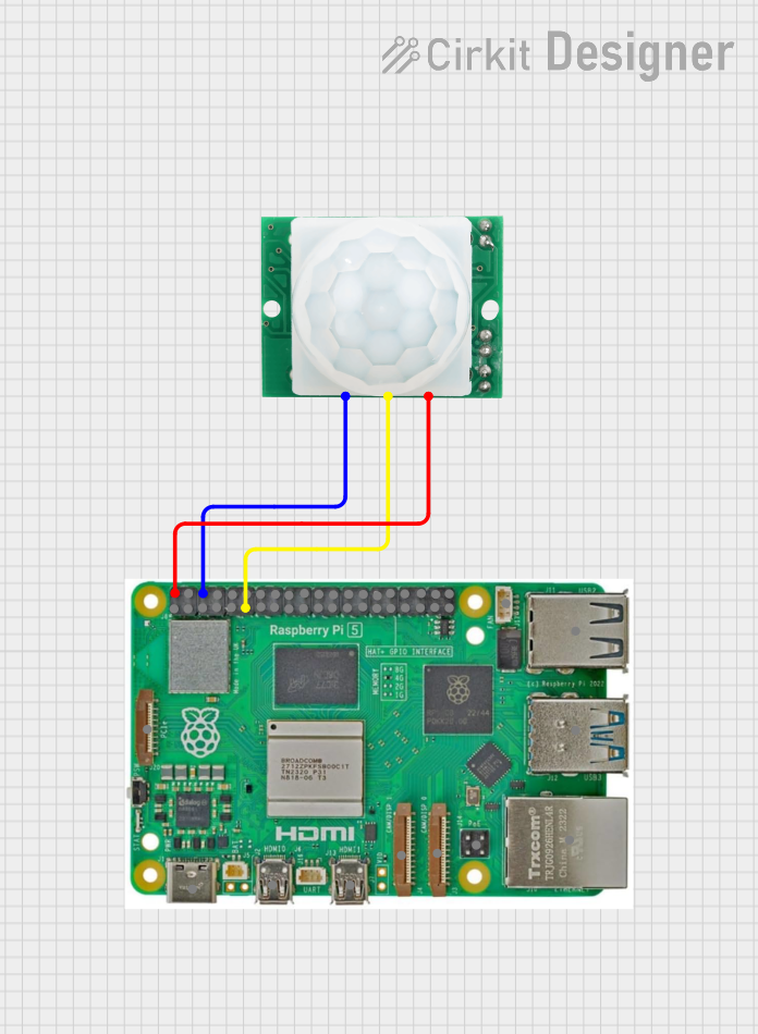
Pin Configuration and Descriptions

Pin Number Name Description
1 VCC Power supply input (4.5V to 20V)
2 OUT Output signal (High/Low)
3 GND Ground connection

Usage Instructions

Integration with a Circuit

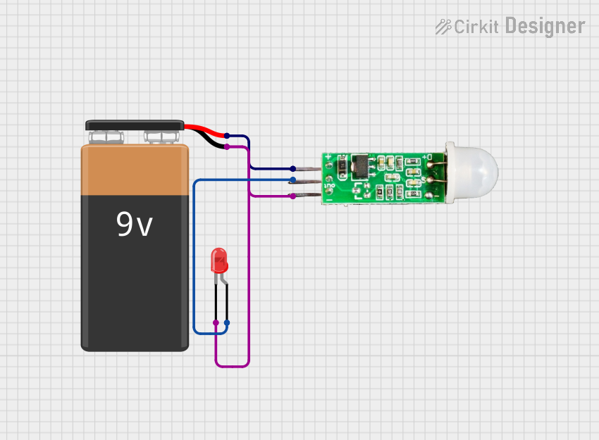
  1. Connect the VCC pin to a power supply within the range of 4.5V to 20V.
  2. Connect the GND pin to the ground of the power supply.
  3. Connect the OUT pin to a digital input pin on the microcontroller.

Important Considerations and Best Practices

  • Ensure that the power supply voltage does not exceed the maximum rating of 20V.
  • Avoid placing the sensor in an environment with rapid temperature changes to prevent false triggers.
  • The sensor may require up to 60 seconds to calibrate upon initial power-up. During this time, it may trigger randomly.
  • Adjust the delay time and trigger method using the onboard potentiometers to suit your application needs.
  • Use appropriate pull-up or pull-down resistors on the OUT pin if required by your microcontroller.

Example Code for Arduino UNO

// HC-SR501 Motion Sensor Example Code
int ledPin = 13; // LED connected to digital pin 13
int sensorPin = 2; // HC-SR501 OUT pin connected to digital pin 2
int sensorState = LOW; // Variable for reading the sensor status

void setup() {
  pinMode(ledPin, OUTPUT); // Initialize the LED pin as an output
  pinMode(sensorPin, INPUT); // Initialize the sensor pin as an input
  Serial.begin(9600); // Start serial communication at 9600 baud
}

void loop() {
  sensorState = digitalRead(sensorPin); // Read the state of the sensor
  if (sensorState == HIGH) { // Check if the sensor is triggered
    digitalWrite(ledPin, HIGH); // Turn LED on
    Serial.println("Motion detected!");
    delay(1000); // Wait for 1 second
  } else {
    digitalWrite(ledPin, LOW); // Turn LED off
    Serial.println("Motion ended.");
    delay(1000); // Wait for 1 second
  }
}

Troubleshooting and FAQs

Common Issues

  • Sensor is always triggered: Check if the sensor is in a stable environment and not facing sources of heat or movement.
  • No response from the sensor: Verify connections and ensure that the power supply is within the specified range.
  • False triggers: Adjust the sensitivity and time delay potentiometers on the sensor module.

Solutions and Tips

  • If the sensor LED indicator is always on, try adjusting the sensitivity and delay time potentiometers.
  • Ensure that the sensor is not placed near heating vents, air conditioners, or other sources of infrared radiation.
  • For more reliable operation, allow the sensor to warm up for 1-2 minutes after powering up.

FAQs

Q: Can the HC-SR501 sensor work with battery power? A: Yes, as long as the battery voltage is within the 4.5V to 20V range.

Q: How can I adjust the sensor's sensitivity? A: Turn the sensitivity adjustment potentiometer on the sensor module.

Q: Is it possible to use the HC-SR501 sensor outdoors? A: The sensor is not weatherproof, so it is not recommended for outdoor use without proper housing.

Q: How do I know if the sensor has stabilized after power-up? A: The sensor typically takes up to 60 seconds to stabilize. During this time, the output may trigger randomly. After this period, the sensor should operate normally.