
How to Use Piezo Speaker 2: Examples, Pinouts, and Specs

 Design with Piezo Speaker 2 in Cirkit Designer
Introduction
A piezo speaker is a type of loudspeaker that uses the piezoelectric effect to produce sound. It converts electrical energy into mechanical energy, creating sound waves through the vibration of a piezoelectric material. The Piezo Speaker 2 is a compact and efficient sound-producing component commonly used in electronic circuits for generating tones, alarms, and beeps.
Explore Projects Built with Piezo Speaker 2
 Open Project in Cirkit Designer
 Open Project in Cirkit Designer
 Open Project in Cirkit Designer
 Open Project in Cirkit Designer
Explore Projects Built with Piezo Speaker 2
Open Project in Cirkit DesignerOpen Project in Cirkit DesignerOpen Project in Cirkit DesignerOpen Project in Cirkit DesignerCommon Applications and Use Cases
- Alarm systems and security devices
- Timers and clocks
- Notification sounds in appliances
- Musical projects and sound effects in hobby electronics
- Feedback sounds in user interfaces (e.g., button presses)
Technical Specifications
The Piezo Speaker 2 is designed for low-power applications and is easy to integrate into various circuits. Below are its key technical details:
| Parameter | Value |
|---|---|
| Operating Voltage | 3V to 12V |
| Rated Voltage | 5V |
| Current Consumption | ≤ 20 mA |
| Resonant Frequency | 3.5 kHz ± 500 Hz |
| Sound Output Level | ≥ 85 dB at 10 cm (5V input) |
| Operating Temperature | -20°C to +60°C |
| Dimensions | Diameter: 20 mm, Height: 8 mm |
Pin Configuration and Descriptions
The Piezo Speaker 2 typically has two pins for connection:
| Pin | Description |
|---|---|
| Positive (+) | Connect to the positive voltage supply or signal source. |
| Negative (-) | Connect to ground (GND). |
Usage Instructions
How to Use the Piezo Speaker 2 in a Circuit
- Power Supply: Ensure the operating voltage is within the range of 3V to 12V. A common setup uses 5V.
- Connection: Connect the positive pin of the piezo speaker to the signal source (e.g., microcontroller pin or oscillator circuit) and the negative pin to ground.
- Signal Generation: To produce sound, apply a square wave signal to the positive pin. The frequency of the square wave determines the pitch of the sound.
Example Circuit with Arduino UNO
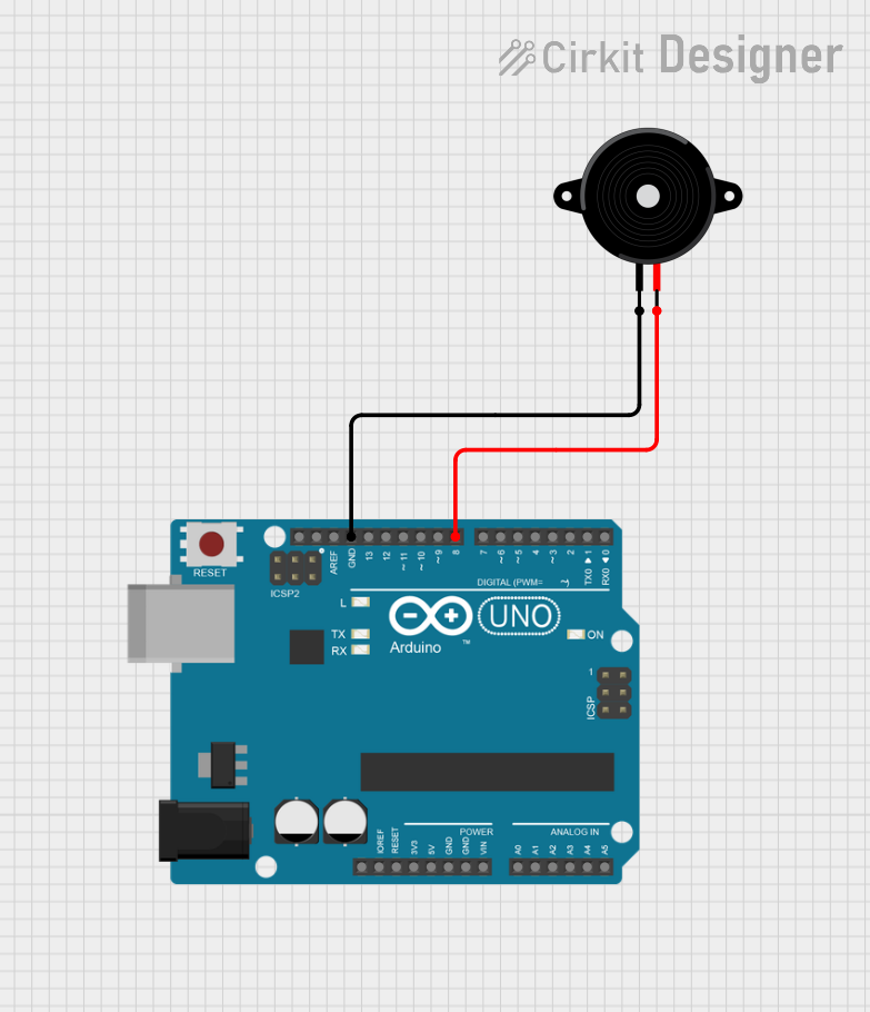
The Piezo Speaker 2 can be easily controlled using an Arduino UNO. Below is an example of generating a simple tone:
// Example: Generate a tone using Piezo Speaker 2 with Arduino UNO
// Connect the positive pin of the piezo speaker to pin 8 on the Arduino
// Connect the negative pin of the piezo speaker to GND

int piezoPin = 8; // Pin connected to the piezo speaker

void setup() {
  pinMode(piezoPin, OUTPUT); // Set the piezo pin as an output
}

void loop() {
  tone(piezoPin, 1000); // Generate a 1 kHz tone
  delay(500);           // Play the tone for 500 ms
  noTone(piezoPin);     // Stop the tone
  delay(500);           // Wait for 500 ms before repeating
}
Important Considerations and Best Practices
- Voltage Limits: Do not exceed the maximum operating voltage of 12V to avoid damaging the component.
- Frequency Range: For optimal sound output, use frequencies close to the resonant frequency (3.5 kHz).
- Current Limiting: If driving the piezo speaker directly from a microcontroller, ensure the current does not exceed the microcontroller's pin limits.
- Mounting: Secure the piezo speaker to a stable surface to prevent unwanted vibrations or noise.
Troubleshooting and FAQs
Common Issues and Solutions
No Sound Output
- Cause: Incorrect wiring or insufficient voltage.
- Solution: Verify the connections and ensure the voltage is within the operating range.
Distorted Sound
- Cause: Signal frequency is too far from the resonant frequency.
- Solution: Adjust the signal frequency closer to 3.5 kHz for better sound quality.
Low Volume
- Cause: Insufficient input voltage or improper mounting.
- Solution: Increase the input voltage (within the safe range) and ensure the speaker is securely mounted.
Overheating
- Cause: Excessive current or prolonged use at high voltage.
- Solution: Use a current-limiting resistor and avoid exceeding the maximum voltage.
FAQs
Q: Can I use the Piezo Speaker 2 with a 3.3V microcontroller?
A: Yes, the Piezo Speaker 2 can operate at 3.3V, but the sound output may be quieter compared to 5V operation.
Q: How do I generate different tones?
A: Vary the frequency of the square wave signal applied to the piezo speaker. For example, in Arduino, you can use the tone() function with different frequency values.
Q: Can the Piezo Speaker 2 produce continuous sound?
A: Yes, by applying a continuous square wave signal, the piezo speaker will produce a continuous tone.
Q: Is the Piezo Speaker 2 waterproof?
A: No, the Piezo Speaker 2 is not waterproof. Avoid exposing it to moisture or water.
By following this documentation, you can effectively integrate the Piezo Speaker 2 into your projects and troubleshoot common issues with ease.