
How to Use USB UART: Examples, Pinouts, and Specs
 Design with USB UART in Cirkit Designer
Introduction
The FT232RL, manufactured by FTDI Chip, is a USB to Universal Asynchronous Receiver-Transmitter (UART) converter. It enables seamless serial communication between a computer and microcontrollers, sensors, or other devices via a USB interface. This component is widely used in embedded systems, prototyping, and debugging applications due to its reliability and ease of use.
Explore Projects Built with USB UART
 Open Project in Cirkit Designer
 Open Project in Cirkit Designer
 Open Project in Cirkit Designer
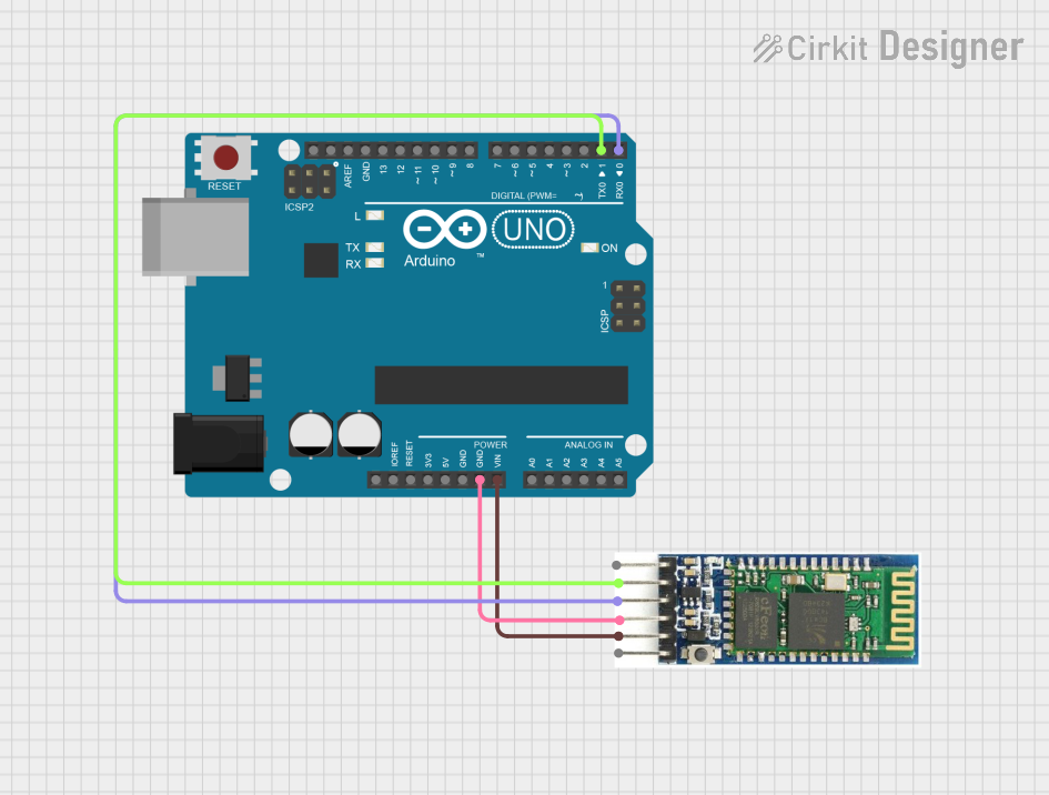 Open Project in Cirkit Designer
Explore Projects Built with USB UART
Open Project in Cirkit DesignerOpen Project in Cirkit DesignerOpen Project in Cirkit DesignerOpen Project in Cirkit DesignerCommon Applications
- USB-to-serial communication for microcontrollers (e.g., Arduino, PIC, AVR)
- Debugging and programming embedded systems
- Interfacing legacy serial devices with modern computers
- USB-based data logging and monitoring systems
Technical Specifications
Key Technical Details
| Parameter | Value |
|---|---|
| Manufacturer | FTDI Chip |
| Part Number | FT232RL |
| USB Interface | USB 2.0 Full Speed (12 Mbps) |
| UART Baud Rate | Up to 3 Mbps |
| Operating Voltage | 3.3V (core) / 5V (I/O, USB VBUS) |
| Power Consumption | ~15 mA (typical) |
| Operating Temperature | -40°C to +85°C |
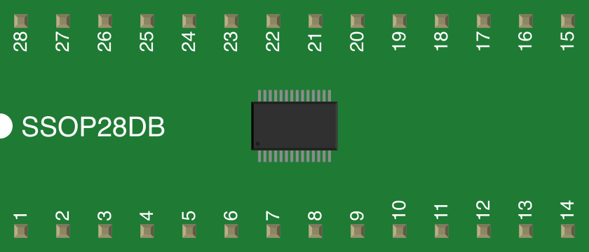
| Package Type | SSOP-28 |
| Integrated Features | EEPROM, TX/RX LEDs, and voltage regulator |
Pin Configuration and Descriptions
The FT232RL comes in a 28-pin SSOP package. Below is the pinout and description:
| Pin No. | Pin Name | Description |
|---|---|---|
| 1 | TXD | Transmit Data (UART output) |
| 2 | RXD | Receive Data (UART input) |
| 3 | RTS# | Request to Send (active low) |
| 4 | CTS# | Clear to Send (active low) |
| 5 | DTR# | Data Terminal Ready (active low) |
| 6 | DSR# | Data Set Ready (active low) |
| 7 | DCD# | Data Carrier Detect (active low) |
| 8 | RI# | Ring Indicator (active low) |
| 9 | VCC | 3.3V Core Supply Voltage |
| 10 | GND | Ground |
| 11 | USB D+ | USB Data Positive |
| 12 | USB D- | USB Data Negative |
| 13 | VBUS | USB Bus Power Supply (5V) |
| 14 | 3V3OUT | 3.3V Regulated Output (can supply up to 50 mA) |
| 15 | RESET# | Active Low Reset Input |
| 16 | TEST | Test Pin (leave unconnected in normal operation) |
| 17 | EEPROM | EEPROM Interface Pins (used for configuration) |
| 18-28 | Miscellaneous | Other pins for advanced configurations (refer to the FTDI datasheet) |
Usage Instructions
How to Use the FT232RL in a Circuit
- Power Supply: Connect the VBUS pin to the USB 5V supply and GND to ground. The FT232RL has an internal voltage regulator that provides 3.3V output on the 3V3OUT pin.
- USB Connection: Connect the USB D+ and USB D- pins to the corresponding USB data lines.
- UART Interface: Connect the TXD and RXD pins to the UART pins of your microcontroller or device. Ensure proper voltage levels for UART communication.
- Optional Control Signals: Use RTS#, CTS#, DTR#, and other control pins as needed for hardware flow control.
- Driver Installation: Install the FTDI drivers on your computer to enable USB-to-serial communication. These drivers are available for Windows, macOS, and Linux.
Important Considerations
- Voltage Levels: Ensure that the UART pins of the connected device are compatible with the FT232RL's I/O voltage (3.3V or 5V).
- Driver Configuration: Use the FTDI-provided configuration utility to customize the EEPROM settings if needed.
- Bypass Capacitors: Place decoupling capacitors (e.g., 0.1 µF) near the VCC and GND pins for stable operation.
- USB Cable Quality: Use a high-quality USB cable to avoid communication errors.
Example: Connecting FT232RL to Arduino UNO
The FT232RL can be used to program or communicate with an Arduino UNO. Below is an example Arduino sketch for serial communication:
// Example: Serial Communication with FT232RL
// This sketch sends "Hello, FT232RL!" to the serial monitor every second.

void setup() {
  Serial.begin(9600); // Initialize serial communication at 9600 baud
}

void loop() {
  Serial.println("Hello, FT232RL!"); // Send message to serial monitor
  delay(1000); // Wait for 1 second
}
Troubleshooting and FAQs
Common Issues
Device Not Recognized by Computer
- Cause: Missing or incorrect FTDI drivers.
- Solution: Download and install the latest drivers from the FTDI Chip website.
No Data Transmission
- Cause: Incorrect TXD/RXD connections or mismatched baud rate.
- Solution: Verify the TXD and RXD connections and ensure the baud rate matches on both ends.
Overheating
- Cause: Excessive current draw or incorrect wiring.
- Solution: Check the circuit for shorts and ensure the connected devices do not exceed the FT232RL's current limits.
Communication Errors
- Cause: Poor USB cable quality or electrical noise.
- Solution: Use a shielded USB cable and ensure proper grounding.
FAQs
Q: Can the FT232RL be used with 5V logic devices?
A: Yes, the FT232RL supports both 3.3V and 5V logic levels for UART communication.
Q: How do I reset the FT232RL?
A: Pull the RESET# pin low momentarily to reset the device.
Q: Is the FT232RL compatible with Linux?
A: Yes, the FT232RL is fully compatible with Linux, and most distributions include built-in support for FTDI devices.
Q: Can I use the FT232RL to power my microcontroller?
A: Yes, the 3V3OUT pin can supply up to 50 mA, which is sufficient for low-power microcontrollers.