
How to Use Buzzer 12mm: Examples, Pinouts, and Specs
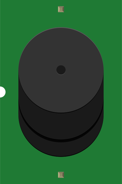
 Design with Buzzer 12mm in Cirkit Designer
Introduction
The Buzzer 12mm by SparkFun Electronics is a small, cylindrical sound-emitting device designed to produce sound when an electrical signal is applied. It is commonly used in applications requiring audible alerts, such as alarms, notifications, timers, and user feedback systems. Its compact size and ease of use make it a popular choice for hobbyists and professionals alike.
Explore Projects Built with Buzzer 12mm
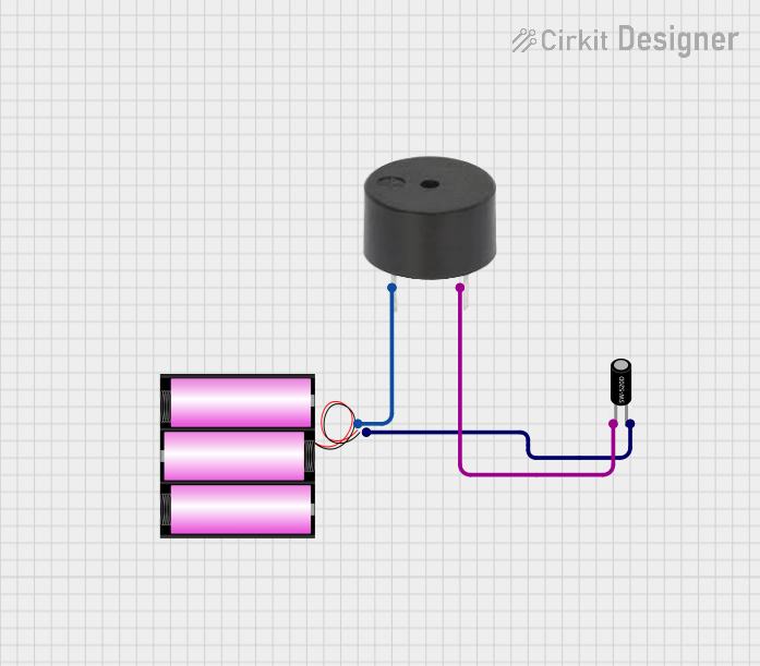 Open Project in Cirkit Designer
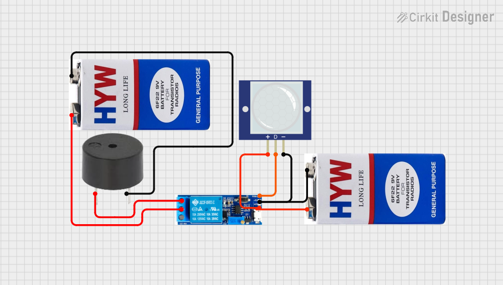 Open Project in Cirkit Designer
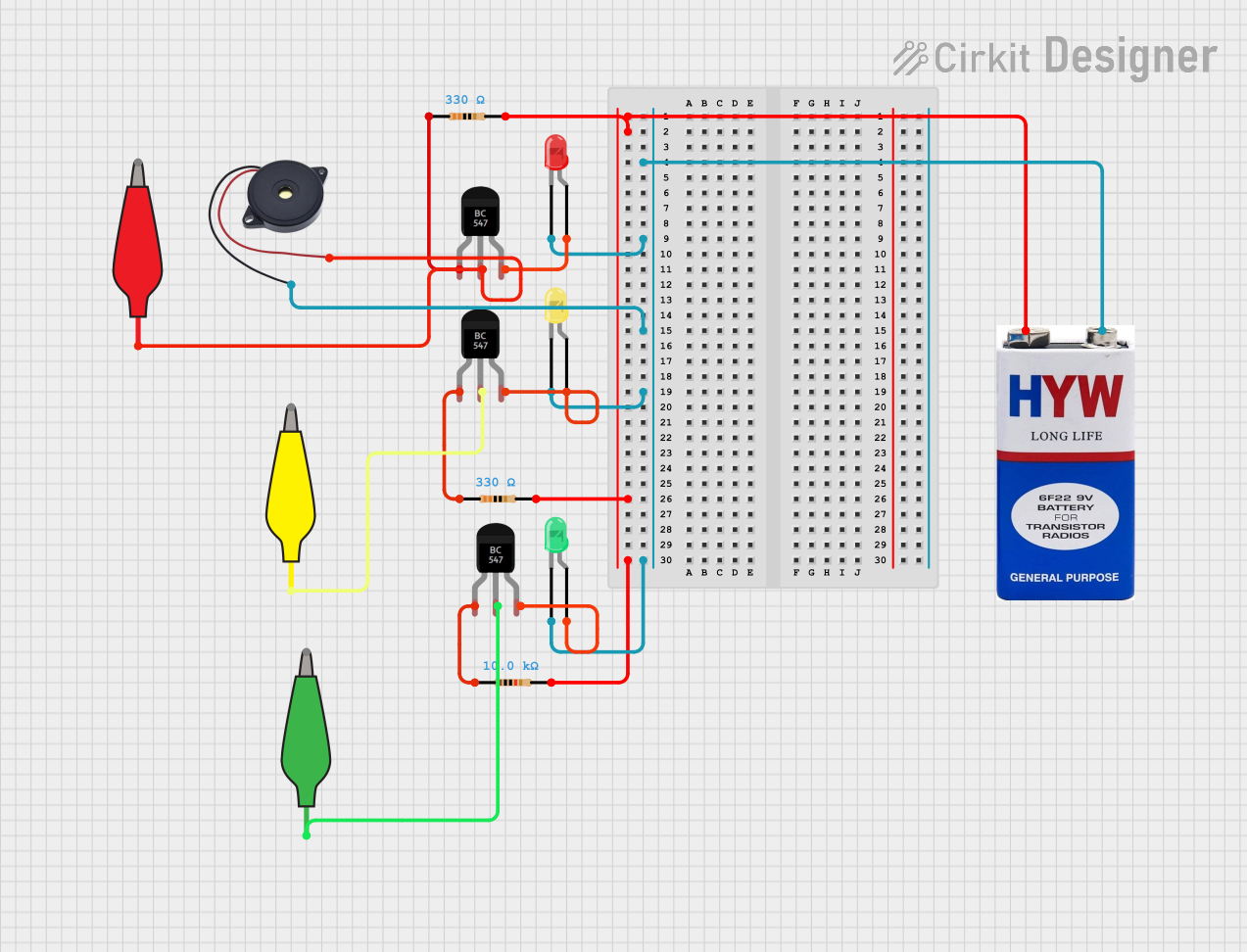 Open Project in Cirkit Designer
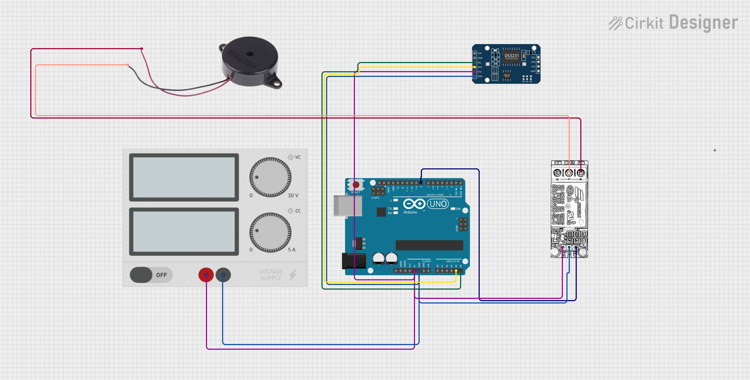 Open Project in Cirkit Designer
Explore Projects Built with Buzzer 12mm
Open Project in Cirkit DesignerOpen Project in Cirkit DesignerOpen Project in Cirkit DesignerOpen Project in Cirkit DesignerCommon Applications
- Alarm systems (e.g., burglar alarms, fire alarms)
- Timers and reminders
- User interface feedback (e.g., button presses)
- Toys and educational projects
- Arduino and microcontroller-based projects
Technical Specifications
Below are the key technical details for the Buzzer 12mm:
| Parameter | Value |
|---|---|
| Operating Voltage | 3V to 12V DC |
| Rated Voltage | 5V DC |
| Current Consumption | ≤ 30mA |
| Sound Output | 85 dB at 10cm (at 5V DC) |
| Resonant Frequency | 2.3 kHz |
| Dimensions | 12mm diameter, 9mm height |
| Operating Temperature | -20°C to +60°C |
| Weight | ~2 grams |
Pin Configuration
The Buzzer 12mm has two pins for electrical connections:
| Pin | Description | Polarity |
|---|---|---|
| Pin 1 | Positive terminal (+) | Positive |
| Pin 2 | Negative terminal (-) | Ground |
Note: The positive terminal is usually marked with a "+" symbol or a longer pin.
Usage Instructions
How to Use the Buzzer in a Circuit
- Power Requirements: Ensure the buzzer is powered within its operating voltage range (3V to 12V DC). Exceeding this range may damage the component.
- Polarity: Connect the positive terminal of the buzzer to the positive voltage supply and the negative terminal to ground.
- Control Signal: To produce sound, apply a DC voltage or a square wave signal to the positive terminal. A square wave signal allows you to control the tone and frequency of the sound.
- Resistor (Optional): If using a higher voltage (e.g., 12V), consider adding a current-limiting resistor in series to prevent excessive current draw.
Example Circuit with Arduino UNO
The following example demonstrates how to connect and control the Buzzer 12mm using an Arduino UNO:
Circuit Connections
- Connect the positive terminal of the buzzer to Arduino pin 8.
- Connect the negative terminal of the buzzer to the Arduino GND pin.
Arduino Code
// Buzzer 12mm Example Code
// This code generates a tone on the buzzer connected to pin 8 of the Arduino UNO.

#define BUZZER_PIN 8  // Define the pin connected to the buzzer

void setup() {
  pinMode(BUZZER_PIN, OUTPUT);  // Set the buzzer pin as an output
}

void loop() {
  digitalWrite(BUZZER_PIN, HIGH);  // Turn the buzzer ON
  delay(500);                      // Wait for 500 milliseconds
  digitalWrite(BUZZER_PIN, LOW);   // Turn the buzzer OFF
  delay(500);                      // Wait for 500 milliseconds
}
Tip: To produce different tones, you can use the
tone()function in Arduino. For example:tone(BUZZER_PIN, 2300);generates a 2.3 kHz tone.
Important Considerations
- Power Supply: Ensure the power supply is stable and within the specified voltage range.
- Mounting: Secure the buzzer in place to prevent vibrations from affecting sound quality.
- Noise Sensitivity: Avoid placing the buzzer near sensitive components that may be affected by its sound or vibrations.
Troubleshooting and FAQs
Common Issues and Solutions
No Sound from the Buzzer
- Cause: Incorrect polarity or insufficient voltage.
- Solution: Verify the connections and ensure the voltage is within the operating range.
Low or Distorted Sound
- Cause: Insufficient current or incorrect frequency.
- Solution: Check the power supply and ensure the control signal matches the buzzer's resonant frequency (2.3 kHz).
Buzzer Overheats
- Cause: Excessive voltage or current.
- Solution: Use a current-limiting resistor or reduce the supply voltage.
Intermittent Sound
- Cause: Loose connections or unstable power supply.
- Solution: Secure all connections and use a stable power source.
FAQs
Q1: Can I use the Buzzer 12mm with a 3.3V microcontroller?
A1: Yes, the buzzer can operate at 3.3V, but the sound output may be lower compared to 5V operation.
Q2: How do I produce different tones with the buzzer?
A2: Use a square wave signal with varying frequencies. In Arduino, you can use the tone() function to generate specific frequencies.
Q3: Is the Buzzer 12mm waterproof?
A3: No, the Buzzer 12mm is not waterproof. Avoid exposing it to moisture or water.
Q4: Can I use the buzzer for continuous sound output?
A4: Yes, the buzzer can operate continuously as long as the voltage and current are within the specified range.
By following this documentation, you can effectively integrate the Buzzer 12mm into your projects and troubleshoot any issues that arise.