How to Use max30120: Examples, Pinouts, and Specs
Introduction
The MAX30120 is a low-power, integrated pulse oximeter and heart-rate monitor sensor. It is designed for wearable applications and provides accurate measurements of blood oxygen saturation (SpO2) and heart rate using photoplethysmography (PPG) technology. This compact sensor is ideal for health monitoring devices, fitness trackers, and other portable applications where low power consumption and high accuracy are critical.
Explore Projects Built with max30120


Explore Projects Built with max30120
Common Applications and Use Cases
- Wearable health monitoring devices
- Fitness trackers
- Medical devices for SpO2 and heart rate measurement
- IoT-based health monitoring systems
- Research and development in biomedical engineering
Technical Specifications
The MAX30120 is a highly integrated sensor with advanced features for precise and reliable measurements. Below are its key technical specifications:
Key Technical Details
| Parameter | Value |
|---|---|
| Supply Voltage | 1.8V (core) and 3.3V (I/O) |
| Operating Current | 5.7µA (typical, in low-power mode) |
| Measurement Technology | Photoplethysmography (PPG) |
| SpO2 Measurement Range | 0% to 100% |
| Heart Rate Measurement Range | 30 bpm to 240 bpm |
| LED Wavelengths | Red: 660nm, IR: 880nm |
| Communication Interface | I²C (up to 400kHz) |
| Package Size | 2.9mm x 4.3mm x 1.4mm |
| Operating Temperature Range | -40°C to +85°C |
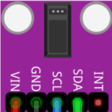
Pin Configuration and Descriptions
The MAX30120 has a compact package with the following pin configuration:
| Pin Number | Pin Name | Description |
|---|---|---|
| 1 | VDD | Power supply for the core (1.8V) |
| 2 | GND | Ground |
| 3 | SDA | I²C data line |
| 4 | SCL | I²C clock line |
| 5 | INT | Interrupt output (active low) |
| 6 | VLED | Power supply for LEDs (3.3V) |
| 7 | NC | No connection (leave unconnected) |
Usage Instructions
The MAX30120 is straightforward to use in a circuit, but proper setup and configuration are essential for accurate measurements. Below are the steps and best practices for using the sensor:
How to Use the Component in a Circuit
- Power Supply: Connect the VDD pin to a 1.8V power source and the VLED pin to a 3.3V power source. Ensure a stable power supply to avoid measurement errors.
- I²C Communication: Connect the SDA and SCL pins to the corresponding I²C pins on your microcontroller. Use pull-up resistors (typically 4.7kΩ) on both lines.
- Interrupt Pin: Connect the INT pin to a GPIO pin on your microcontroller if you want to use interrupt-driven data reading.
- Ground Connection: Connect the GND pin to the ground of your circuit.
- LED Configuration: The MAX30120 uses internal LEDs for PPG measurements. No external LEDs are required.
Important Considerations and Best Practices
- Placement: For wearable applications, ensure the sensor is in direct contact with the skin for accurate readings.
- Ambient Light: Minimize ambient light interference by using an opaque enclosure or covering the sensor.
- I²C Address: The default I²C address of the MAX30120 is
0x57. Ensure no address conflicts with other devices on the I²C bus. - Initialization: Configure the sensor's registers during initialization to set the desired measurement mode, LED current, and sampling rate.
Example Code for Arduino UNO
Below is an example of how to interface the MAX30120 with an Arduino UNO to read heart rate and SpO2 data:
#include <Wire.h>

// MAX30120 I2C address
#define MAX30120_ADDRESS 0x57

void setup() {
  Wire.begin(); // Initialize I2C communication
  Serial.begin(9600); // Initialize serial communication for debugging

  // Initialize MAX30120
  if (!initializeMAX30120()) {
    Serial.println("MAX30120 initialization failed!");
    while (1); // Halt execution if initialization fails
  }
  Serial.println("MAX30120 initialized successfully.");
}

void loop() {
  // Read data from MAX30120
  uint8_t redData, irData;
  if (readMAX30120Data(&redData, &irData)) {
    Serial.print("Red LED Data: ");
    Serial.print(redData);
    Serial.print(" | IR LED Data: ");
    Serial.println(irData);
  } else {
    Serial.println("Failed to read data from MAX30120.");
  }
  delay(1000); // Wait 1 second before the next reading
}

bool initializeMAX30120() {
  Wire.beginTransmission(MAX30120_ADDRESS);
  Wire.write(0x09); // Example register address for initialization
  Wire.write(0x03); // Example configuration value
  return (Wire.endTransmission() == 0); // Return true if successful
}

bool readMAX30120Data(uint8_t *red, uint8_t *ir) {
  Wire.beginTransmission(MAX30120_ADDRESS);
  Wire.write(0x05); // Example register address for data
  if (Wire.endTransmission(false) != 0) return false; // Restart condition
  Wire.requestFrom(MAX30120_ADDRESS, 2); // Request 2 bytes of data
  if (Wire.available() < 2) return false; // Check if data is available
  *red = Wire.read(); // Read red LED data
  *ir = Wire.read(); // Read IR LED data
  return true; // Return true if successful
}
Troubleshooting and FAQs
Common Issues Users Might Face
No Data Output:
- Ensure the sensor is powered correctly (1.8V for VDD and 3.3V for VLED).
- Verify the I²C connections and pull-up resistors.
- Check the I²C address (
0x57) and ensure no conflicts with other devices.
Inaccurate Measurements:
- Ensure the sensor is in direct contact with the skin.
- Minimize ambient light interference by using an opaque cover.
- Verify the sensor's configuration registers for correct settings.
I²C Communication Errors:
- Check the SDA and SCL connections for loose or incorrect wiring.
- Ensure the I²C clock speed does not exceed 400kHz.
Solutions and Tips for Troubleshooting
- Use a logic analyzer or oscilloscope to debug I²C communication issues.
- Test the sensor with a known good microcontroller and code to isolate hardware issues.
- Refer to the MAX30120 datasheet for detailed register descriptions and configuration options.